

Voltage dependent resistor with hot protection function
A varistor and thermal protection technology, applied in varistor, overvoltage protection resistors, resistors, etc., can solve the problems of easy failure, inconvenience, fire and burning, etc., to achieve protection from damage and increase the thermal conductivity area. Effect
- Summary
- Abstract
- Description
- Claims
- Application Information
AI Technical Summary
Problems solved by technology
Method used
Image

Examples
Embodiment Construction
[0042] In order to further explain the technical means and effects of the present invention to achieve the intended purpose of the invention, the specific implementation, structure, Features and their functions are described in detail below.
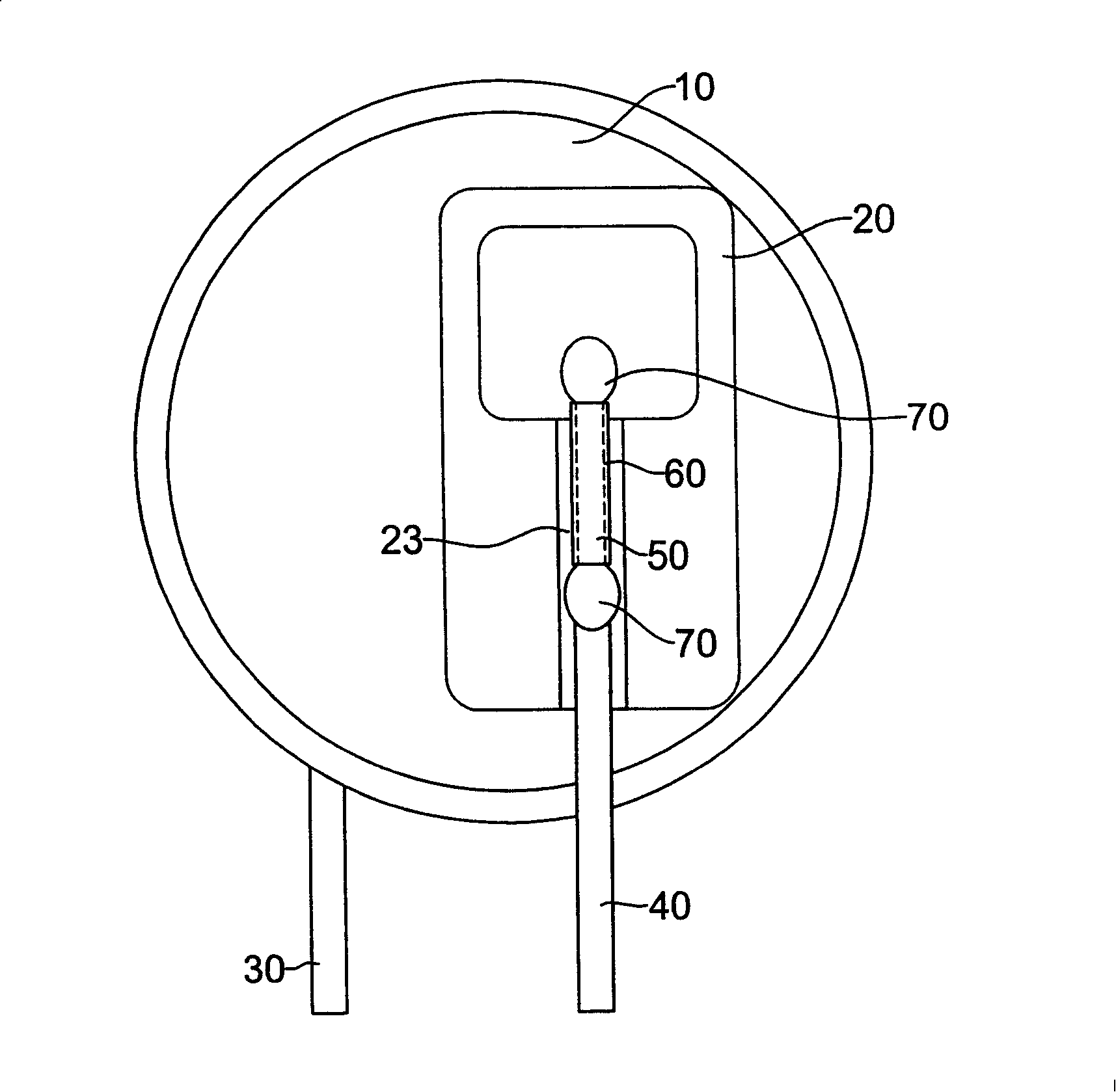
[0043] see figure 1 As shown, the first embodiment of the present invention includes a body 10 , an insulating support 20 , a first pin 30 and a second pin 40 .
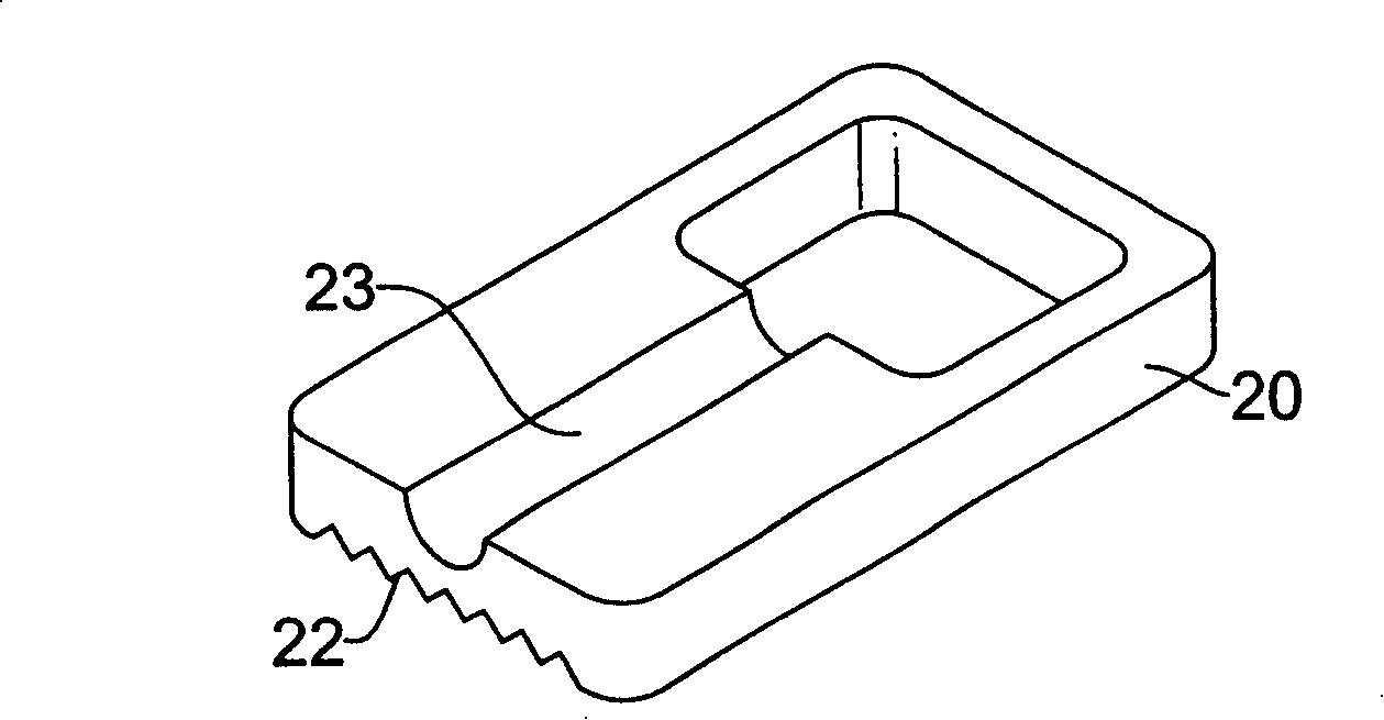
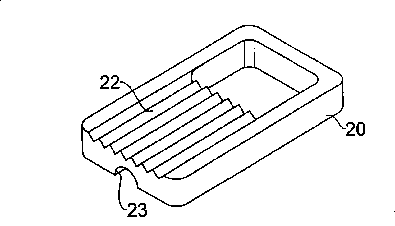
[0044] see Figure 1 to Figure 3 As shown, the aforementioned insulating bracket 20 can be a ceramic material with good thermal conductivity. The insulating bracket 20 is arranged on one side of the body 10. The side where the insulating bracket 20 connects with the body 10 is concavely formed with a plurality of serrated grooves 22. The side of the insulating bracket 20 different from that of the main body 10 is concavely formed with a receiving slot 23 .
[0045] see figure 1 and Figure 4 As shown, the aforementioned first pin 30 is electrically connected to the side of...
PUM
 Abstract
Description
Claims
Application Information