Non-contact tonometery and device

A measurement method and non-contact technology, applied in the direction of tonometer, etc., can solve the problems of complex structure, complex corneal alignment system, complex design, etc., and achieve the effect of simple overall structure design, effective intraocular pressure measurement, and low production cost.

Inactive Publication Date: 2008-06-25
CHONGQING UNIV
View PDF2 Cites 11 Cited by
  • Summary
  • Abstract
  • Description
  • Claims
  • Application Information

AI Technical Summary

Problems solved by technology

This measurement method is an indirect measurement method, and this type of non-contact tonometer cannot guarantee that when the cornea is sprayed by fluid to the rated area, the pressure or time change measured by the pressure sensor in the air cavity is the measured accurate intraocular pressure value , the determination of intraocular pressure needs to be corrected through experiments or realized through related complex algorithms
[0005] Furthermore, the corneal alignment system in the existing non-contact tonometer is relatively complicated. For example, the Chinese patent No. 03157025.9 uses a large number of optical elements and imaging systems to achieve the purpose of aligning the measured cornea.
In NO.02822091.9, the structure is more complex. The design of the corneal alignment system involves image processing and requires a corresponding calibration system to help complete the corneal alignment. A large number of optical elements are used in it.
These designs are complex, expensive to manufacture, and expensive to produce
[0006] In summary, the existing non-contact intraocular pressure measurement methods and devices are usually measured by an indirect method, that is, through an algorithm or correction to make the air cavity internal pressure or the change time of the air cavity internal pressure related to the intraocular pressure value , is not a direct measurement method, and its corneal alignment system has more optical elements and a more complex structure. The existing non-contact intraocular pressure measurement device has high manufacturing cost and expensive production

Method used


Image

  • Non-contact tonometery and device
  • Non-contact tonometery and device
  • Non-contact tonometery and device

Examples


Embodiment Construction

[0032] The present invention will be described in detail based on the illustrated embodiments.

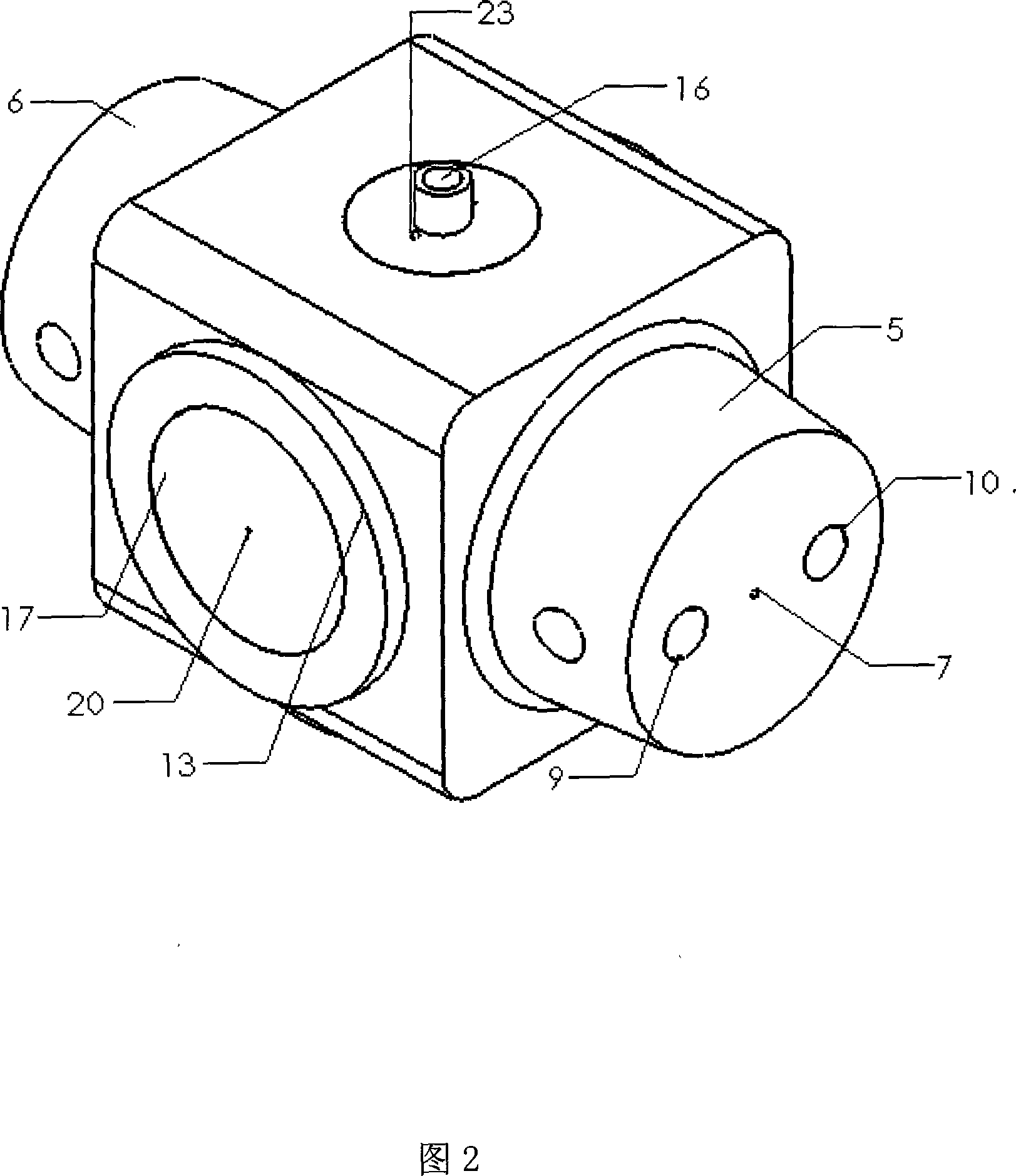
[0033] Figure 2 is a perspective view of the air-floating intraocular pressure measurement module. The front and rear of the air-floating intraocular pressure measurement module are composed of two symmetrical bosses 5 and 6. As shown in Figure 3 and 4, there are nozzles 7 and 8 of the same diameter at the centers of the symmetrical bosses 5 and 6 respectively. , the diameter parameters of the nozzle are designed using the theory of hydrodynamic jet technology, and the nozzles 7 and 8 are connected to the central air cavity 26 designed by the air-floating intraocular pressure measurement module on the same horizontal line. As shown in FIG. 7 , a hole 16 is opened on the top of the air-floating tonometry module, and the hole communicates with the central air cavity 26 . As shown in Figures 5, 6, and 8, the bottom of the air-floating intraocular pressure measurement module has a bos...


PUM


Abstract

The invention provides a non-touch intraocular pressure measuring method and a device thereof, relating to the ophthalmology field of intraocular pressure measurement. The air-float intraocular pressure measurement module is placed inside the shell, the measurement module is designed according to the theory of the aerostatic bearing in the aerodynamic lubrication technology, the pressure sensor is installed in the back wall of the shell, and the shell is fixed on the micromatic setting. The air-float intraocular pressure measurement module reaches the rated measuring distance by adopting the micromatic setting. When the air-float measurement module of the intraocular pressure is on the force balance stage, the rated area of the cornea pressure sprayed from the foreside of the spray nozzle of the air-float intraocular pressure measurement module is balanced with the applied force which is produced by the pressure sprayed from the back spray nozzle of the air-float intraocular pressure measurement module; the processor is controlled by the microprocessor, the applied force is measured by the information processing device and then the intraocular pressure value is displayed. The intraocular pressure value can be directly measured by the invention, at the same time, the whole structure design is simple, the cost of the production is low, and the invention is portable and can be utilized in various intraocular pressure measurements.

Description

technical field [0001] The design of the invention relates to a non-contact intraocular pressure measurement method and device for measuring intraocular pressure values ​​in the ophthalmology department of a hospital. Background technique [0002] The biggest advantage of the non-contact tonometer is that it does not need to contact the cornea when measuring intraocular pressure, will not cause corneal damage, and does not need to inject anesthetics into the eyes, so it is widely used in ophthalmology. [0003] The traditional non-contact tonometer rotates the solenoid to push the piston to compress the air in the cylinder, and then sprays pulsed airflow to the measured cornea to deform the cornea from a normal convex state to a known flat state. When the fluid pulse wears off, the cornea returns to its normal bulging state. At the same time, the measurement light is projected from the light source to the cornea, and the reflected light from the cornea is received by photos...

Claims


Application Information

Patent Timeline
Patent Type & Authority Applications(China)
IPC IPC(8): A61B3/16
Inventor 陈骥赵晓明
Owner CHONGQING UNIV
Why Eureka
Try Eureka