
Method for measuring high resistant static pressure dynamic pressure

A technology of dynamic pressure and measurement method, applied in pressure difference measurement between multiple valves, measurement device, measurement of fluid pressure, etc. , to achieve the effect of simple structure and convenient installation

Inactive Publication Date: 2008-06-25
UNIV OF JINAN
View PDF0 Cites 2 Cited by
  • Summary
  • Abstract
  • Description
  • Claims
  • Application Information

AI Technical Summary

Problems solved by technology

At present, the dynamic pressure sensors on the market are either not sensitive enough, or cannot withstand the high static pressure of the working medium, so they cannot meet the actual production needs

Method used


Image

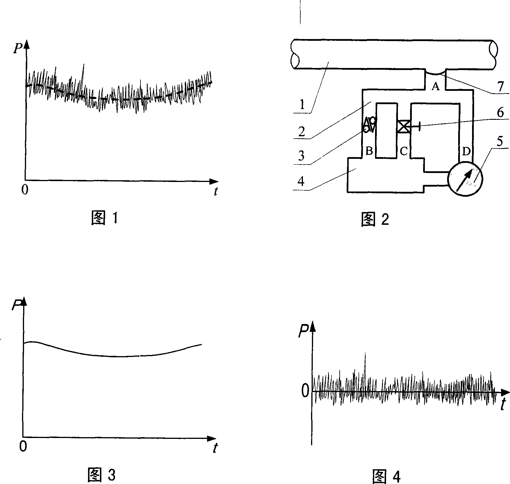
  • Method for measuring high resistant static pressure dynamic pressure

Examples


Embodiment Construction

[0020] The present invention will be further explained and illustrated below in conjunction with the accompanying drawings.

[0021] A method for measuring dynamic pressure with high static pressure resistance. The implementation method is shown in the figure. It sets a side branch channel A connected to the main channel 1. The side branch channel A is set to include a sampling channel D and a damping channel C. The damping channel C passes through the energy storage The device 4 is connected to one side of the differential pressure measurement and transmitter 5, and the sampling channel D is connected to the other side of the differential pressure measurement and transmitter 5, and the pressure signals obtained on both sides are processed by a capacitor bridge and then output. Among them, the differential pressure measurement and transmitter adopt the existing technology, for example: the micro-differential pressure capacitive transmitter with a range of 0-100Pa: 1151DR transm...


PUM


Abstract

The invention relates to the pressure measurement field, in particular to a high static pressure resistant dynamic pressure measurement proposal. The proposal is realized through the following technical measures: a by-pass passage connected with a main passage is provided; the by-pass passage comprises a sampling passage and a damping passage, wherein the damping passage is connected with one side of a differential pressure measuring and transmitting device, the sampling passage is connected with the other side of the differential pressure measuring and transmitting device, and the measured pressure signals on the two sides are outputted after treatment of a capacitance bridge. The proposal has simple method, easy realization, and simple structure and convenient assembly of realization form; the dynamic pressure signals are outputted according to a 4-20mA standard.

Description

technical field [0001] The invention belongs to the field of pressure measurement, in particular to a measurement solution for high static pressure and dynamic pressure. Background technique [0002] As one of the five major means of transportation, pipelines have unique advantages in long-distance transportation of liquids, gases, and slurries, and play an irreplaceable role in industries such as petroleum, chemical, natural gas, and urban water supply. Taking crude oil pipelines as an example, with the increase of pipelines and the growth of pipeline age, pipeline leakage due to natural factors has become increasingly serious, especially in major oil production areas and far-reaching oil and gas pipelines, artificial drilling, Cases of digging holes to steal oil and gas occur frequently, which will not only affect the normal operation of pipeline transportation, but also pollute the environment when transporting toxic, corrosive, flammable and explosive media, causing fire...

Claims


Application Information

Patent Timeline
IPC IPC(8): G01L13/06F17D5/06
Inventor 艾长胜赵洪华孙选王娜李国平初文杰宋磊
Owner UNIV OF JINAN
Learn More