Metal working lubricant formulations based on supercritical carbon dioxide

A carbon dioxide and metal processing technology, applied in relevant problem areas, can solve waste disposal problems, reduce workshop air quality, worker impact and lung impact, etc., to increase tool life and ensure surface finish

Active Publication Date: 2008-06-25
RGT UNIV OF MICHIGAN
View PDF0 Cites 16 Cited by
  • Summary
  • Abstract
  • Description
  • Claims
  • Application Information

AI Technical Summary

Problems solved by technology

The aerosols that can be formed from these oil solutions reduce the air quality in the workplace and in some cases could potentially cause acute and/or chronic skin and pulmonary effects on workers
Oil-in-

Method used


Image

  • Metal working lubricant formulations based on supercritical carbon dioxide
  • Metal working lubricant formulations based on supercritical carbon dioxide
  • Metal working lubricant formulations based on supercritical carbon dioxide

Examples


Embodiment

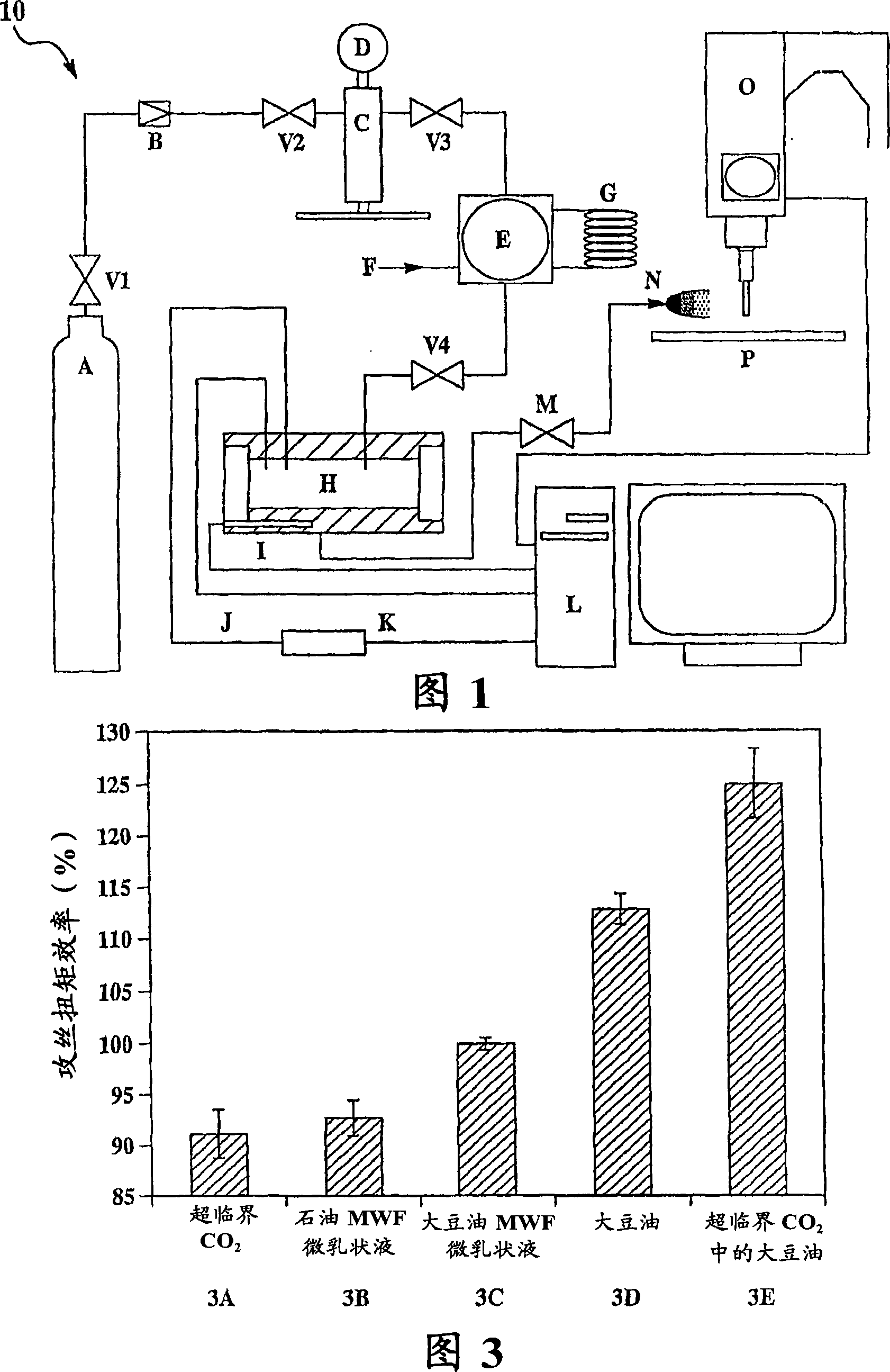
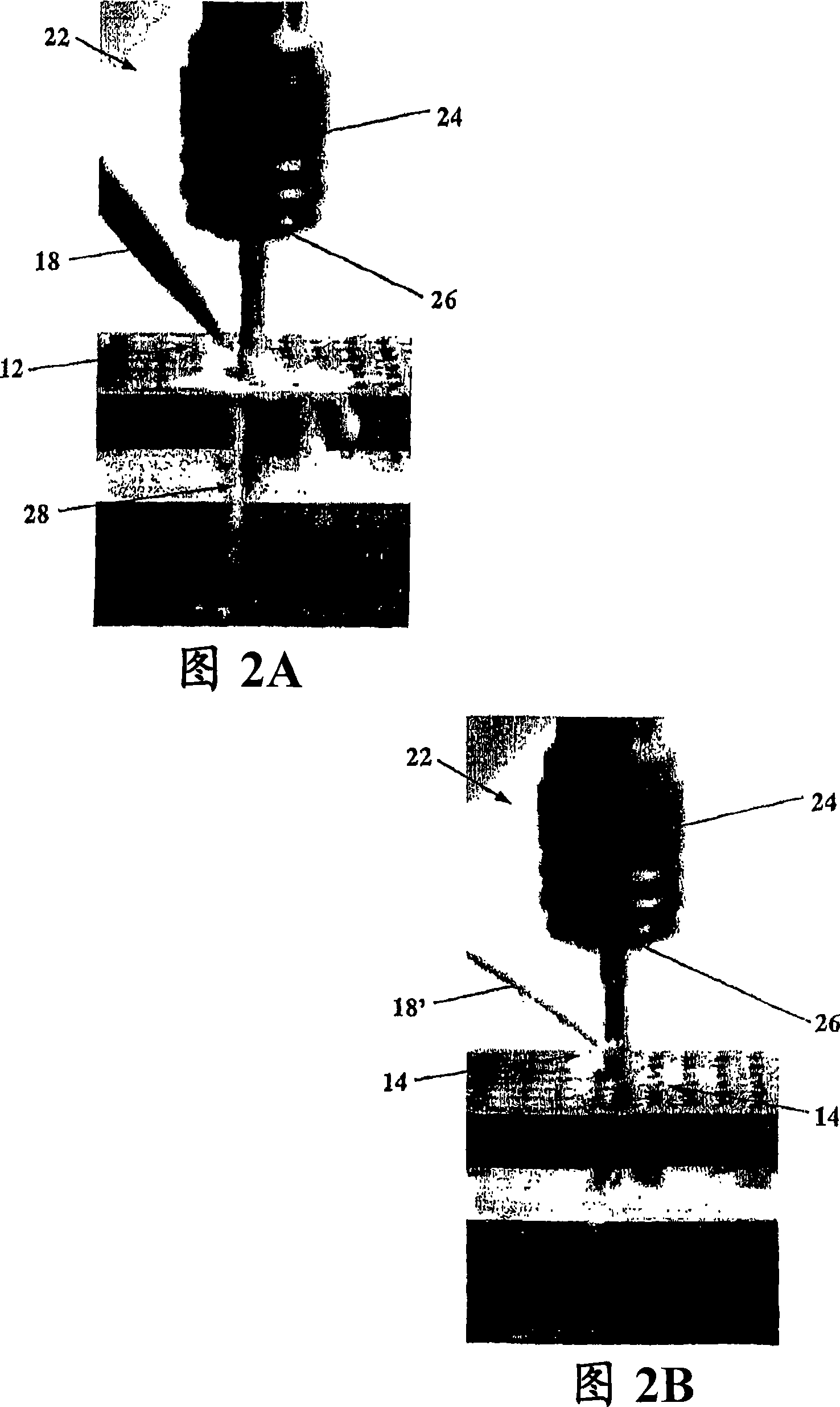
[0041] Tapping torque test method

[0042]The machinability of the MWF developed as disclosed herein was tested by tapping torque using a MicroTap Mega G8 (Rochester Hills, MI) machine tool at a machining speed of 1000 RPM in pre-drilled and pre-reamed 240M6 boreholes ( Maras Tool, Schaumburg, IL) on 1018 steel workpieces. Tapping was performed using an uncoated high speed steel (HSS) tap (for 1018 steel) with a 60° pitch and 3 straight flutes. MWF evaluation was performed according to ASTM D 5619 (the Standard for Comparing Metal Removal Fluid Using the Tapping Torque Test Machine), due to the use of The MWF evaluates the test bed, making several modifications to the standard. MWF performance is reported herein as % tapping torque efficiency (%), which is the average torque measured during full engagement of the tool, normalized to the measured average torque of the reference MWF. Higher efficiency indicates improved performance in the tapping torque test, and has been sho...


PUM


Abstract

A method for lubricating a metal workpiece during a metalworking process includes delivering supercritical carbon dioxide to the workpiece during the metalworking process. The supercritical carbon dioxide acts as a lubricant, coolant, chip evacuator, and/or carrier for another lubricant or corrosion inhibitor.

Description

[0001] Cross References to Related Applications [0002] This application claims the benefit of US Provisional Patent Application Serial No. 60 / 676,531, filed April 29,2005. [0003] Statement Regarding Federally Sponsored Research or Development [0004] This invention was made during research supported by grants from the National Science Foundation (NSF), grant number DMII0093514, and from the National Science Foundation (NSF) / Environmental Protection Agency (EPA), grant number RD 83134701. The US Government has certain rights in this invention. technical background [0005] The present disclosure relates to metalworking, and more particularly to lubricants for metalworking. [0006] Metalworking fluids (MWFs) lubricate and cool metal during a variety of metalworking processes (some non-limiting examples of metalworking processes include cutting processes, forming processes, etc.) and are useful for proper machining function. Specifically, MWF increases tool life, greatly...

Claims


Application Information

Patent Timeline
IPC IPC(8): C10M169/04
CPCC10M2207/04C10M2219/024C10M171/005C10M169/04C10N2270/00C10M2223/04C10M2211/044C10N2250/02C10N2250/04C10M2223/043B23Q11/1053C10M2209/108C10N2220/12C10M2207/0225C10M111/00C10M2203/1006C10M111/02C10M2201/16C10M2207/283C10M2219/08C10N2240/401C10M2207/2805C10M2201/003C10M2219/044C10M2211/022C10M111/04C10M2207/401C10M2201/062C10M2207/1253C10N2230/06C10N2250/06C10M2219/022B23Q11/1061C10N2020/083C10N2030/06C10N2040/22C10N2050/04C10N2050/06C10N2050/01C10N2070/00
Inventor S·J·斯科洛斯K·F·哈耶斯A·克拉伦斯
Owner RGT UNIV OF MICHIGAN
Why Eureka
Try Eureka