Ventilation fermentation tank tail gas energy turbine reclaiming method

A ventilated fermenter and recovery method technology, applied in the field of biochemical engineering, can solve the problems of tail gas pressure energy and heat energy loss, and achieve low equipment cost, lower pressure and temperature, and better effects of energy saving and consumption reduction

Inactive Publication Date: 2008-07-02
吉林巨润生物技术有限公司
View PDF0 Cites 5 Cited by
  • Summary
  • Abstract
  • Description
  • Claims
  • Application Information

AI Technical Summary

Problems solved by technology

Because the exhaust gas has a certain pressure and temperature, this causes the loss of pressure energy and heat energy of the exhaust gas.

Method used


Image

  • Ventilation fermentation tank tail gas energy turbine reclaiming method
  • Ventilation fermentation tank tail gas energy turbine reclaiming method
  • Ventilation fermentation tank tail gas energy turbine reclaiming method

Examples


Embodiment 1

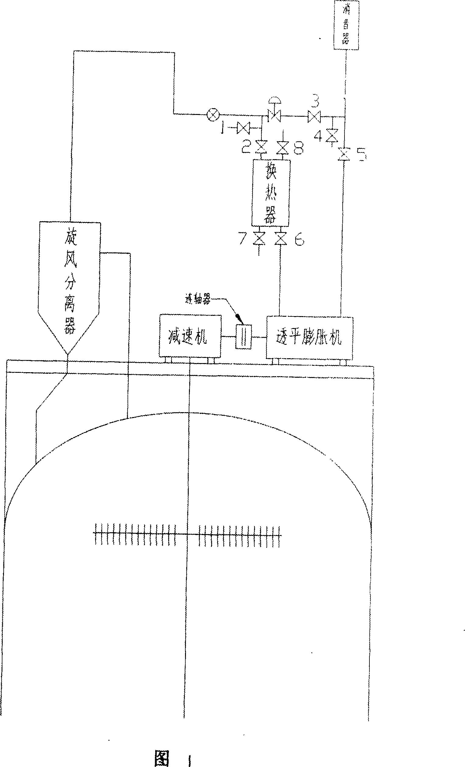
[0017] As shown in Figure 1: Two circuits are connected in parallel on the exhaust pipe of the fermentation tank. One circuit is connected to the heat exchanger and the turbo expander, and the other circuit is connected to the turbo expander at one end and the silencer at the other end. It is connected with the reducer through the coupling. The tail gas from the fermentation tank is introduced into the heat exchanger through valve control. After the tail gas is heated in the heat exchanger, it enters the turbo expander to directly perform work, converts heat and pressure energy into mechanical energy, and outputs the mechanical energy to the reducer to drive the fermentation tank to stir, and the turbine expands After the machine does work, the low-temperature and low-pressure gas is discharged through the valve into the muffler and discharged.

[0018] Close valve 3, lead the tail gas from the fermentation tank through the cyclone separator, enter the heat exchanger through valve...

Embodiment 2

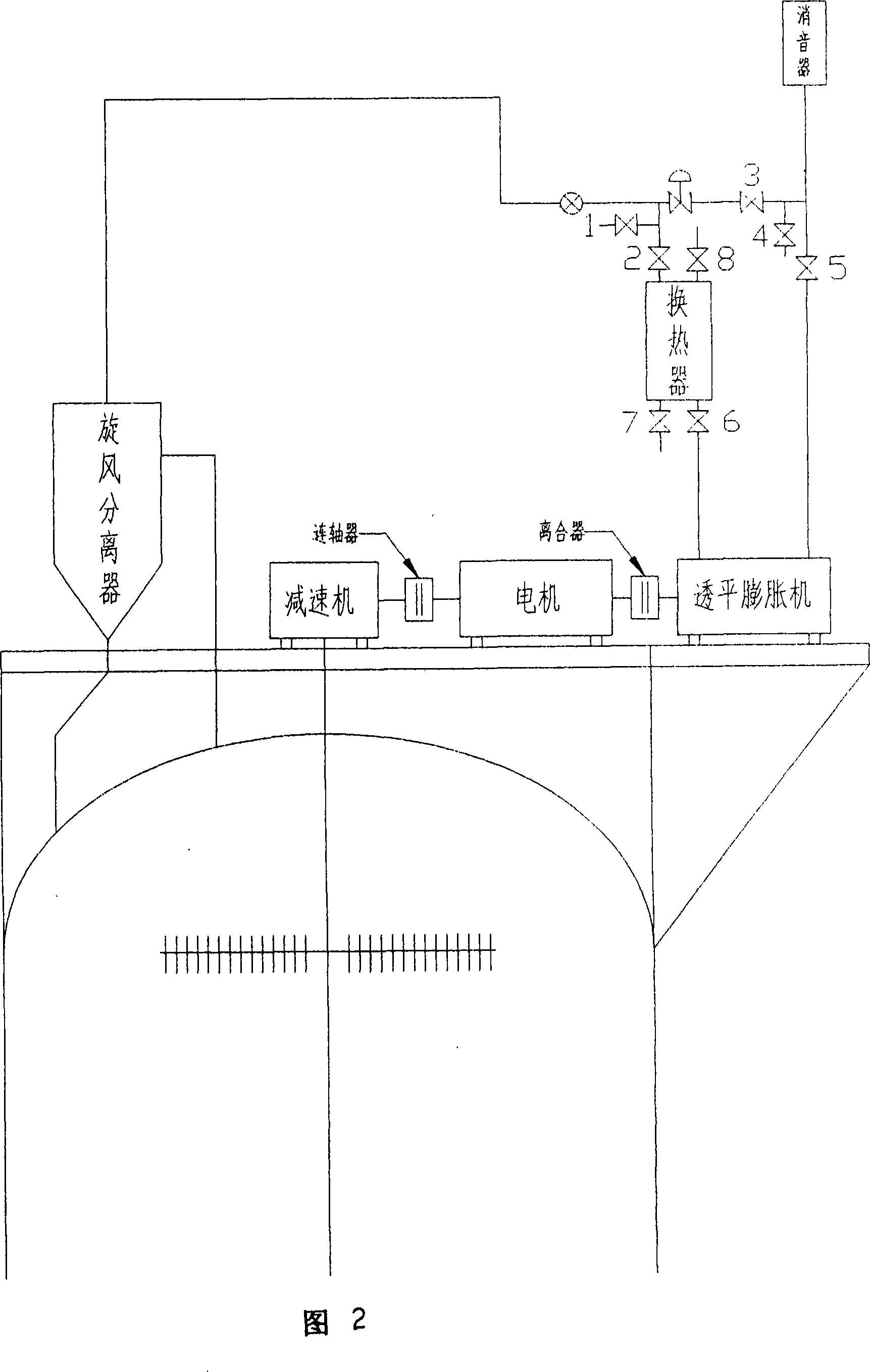
[0020] As shown in Figure 2: Two circuits are connected in parallel on the exhaust pipe of the fermentation tank. One circuit is connected to the heat exchanger and the turbo expander, and the other circuit is connected to the turbo expander at one end and the muffler at the other end. It is connected with the reducer through the coupling. The turbo expander and the reducer can be connected to the motor through a clutch. The tail gas of the fermentation tank is introduced into the heat exchanger through valve control. After the tail gas is heated in the heat exchanger, it enters the turbo expander to directly perform work. The pressure energy is converted into mechanical energy, and the output mechanical energy drives the motor to drive the reducer to stir the fermentation tank; the turbine expands After the machine does work, the low-temperature and low-pressure gas is discharged through the valve into the muffler and discharged.

Embodiment 3

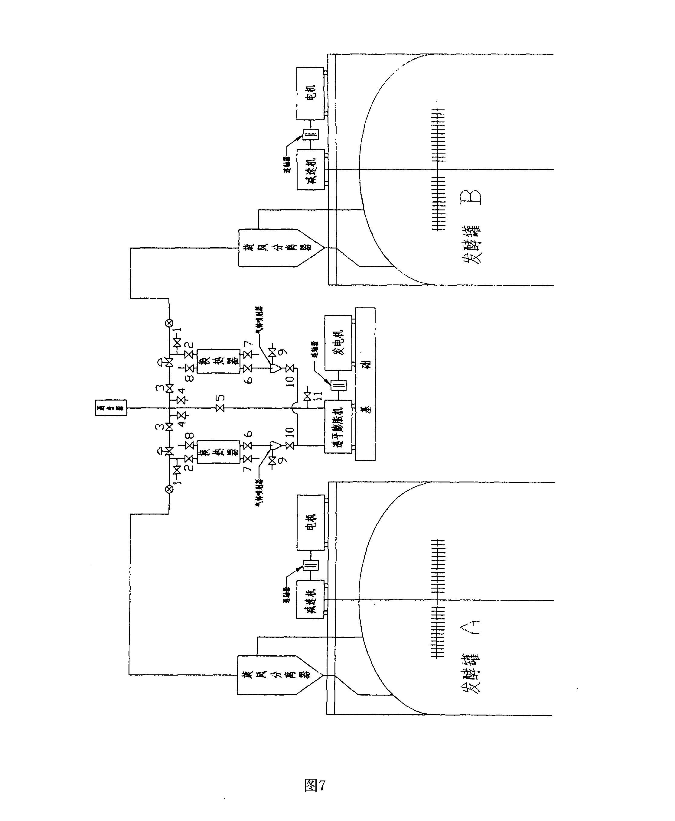
[0022] As shown in Figure 3: Two circuits are connected in parallel on the exhaust pipe of the fermentation tank. One circuit is connected to the heat exchanger and the turbo expander, and the other circuit is connected to the turbo expander at one end and the silencer at the other end. It is connected to the generator through the coupling. The tail gas of the fermentation tank is introduced into the heat exchanger through valve control. After the tail gas is heated in the heat exchanger, it enters the turbo expander to directly perform work, converting heat and pressure energy into mechanical energy, and the output mechanical energy directly drives the generator to generate electricity; the turbo expander does work After that, the low-temperature and low-pressure gas is discharged into the muffler through the valve and discharged.


PUM


Abstract

The invention relates to a method for recovering energy of tail gas of an air-blow fermentation tank by using a turbo-expander. The tail gas in a fermentation tank enters an exhaust pipe through a cyclone and is discharged after silencing by a muffle, and stirring the fermentation tank by a reducer driven by a motor. The method is characterized in that two parallel loops are connected with the exhaust pipe of the fermentation tank; a heat exchanger connected with one loop is connected with the turbo-expander; the other hoop is connected with the turbo-expander and the muffle at both ends; and the turbo-expander is connected with the reducer through a shaft coupler. The pressure and the temperature for gas discharge are reduced, and the waste heat of the liquid and the gas in the production is recovered, thus reasonably utilizing the energy resource. The control system has simple structure, convenient arrangement, good energy saving effect, low equipment cost and low investment.

Description

Technical field [0001] The invention relates to a method for recovering exhaust gas energy from a ventilated fermentation tank, particularly for energy recovery during aerobic biological fermentation, and belongs to the field of biochemical engineering. Background technique [0002] Fermentation companies occupy a very important position in my country's national economy. At the same time, fermentation companies are also large energy consumers. Fermentation is an energy-intensive process, especially aerobic fermentation. It not only uses a lot of steam for the sterilization of equipment and culture medium, but also consumes a lot of power for ventilation, stirring and refrigeration. Therefore, energy saving and consumption reduction of fermentation enterprises are of great significance. [0003] Most industrial fermentation tanks are pure aerobic fermentation. Therefore, the medium used, various equipment and accessories, and the air must be thoroughly sterilized. This is the key ...

Claims


Application Information

Patent Timeline
Patent Type & Authority Applications(China)
IPC IPC(8): C12M1/113
Inventor 王曼丹刘登辉
Owner 吉林巨润生物技术有限公司
Why Eureka
Try Eureka