
Device for treating oil field waste water

A technology for oilfield wastewater and wastewater pools, applied in water/sewage treatment, mining wastewater treatment, multi-stage water/sewage treatment, etc., can solve the problems of poor removal of pollutants in water, difficulty in recycling, high cost of magnetic seeds, etc. Achieve the effects of small footprint, good operability and low power consumption

Active Publication Date: 2008-07-09
溧阳常大技术转移中心有限公司
View PDF1 Cites 26 Cited by
  • Summary
  • Abstract
  • Description
  • Claims
  • Application Information

AI Technical Summary

Problems solved by technology

[0004] Using magnetic materials to treat oilfield wastewater, the most applied and researched at home and abroad is the high-gradient magnetic separator, but there are disadvantages such as complex devices, high power consumption, high cost of magnetic seeds, and difficulty in recycling.
And directly use natural magnetite particles or artificially synthesized Fe 3 o 4 As a magnetic species, magnetic powder has a certain adsorption capacity for pollutants in water, such as bacteria or viruses, turbidity, chroma, oil, heavy metal ions, dissolved organic matter, radioactive pollutants, etc., but when used alone, the removal of pollutants in water The effect is not good. Generally, when adding magnetic seeds to the wastewater, a certain amount of coagulant needs to be added to form magnetic flocculation to remove pollutants.

Method used


Image

  • Device for treating oil field waste water

Examples


Embodiment Construction

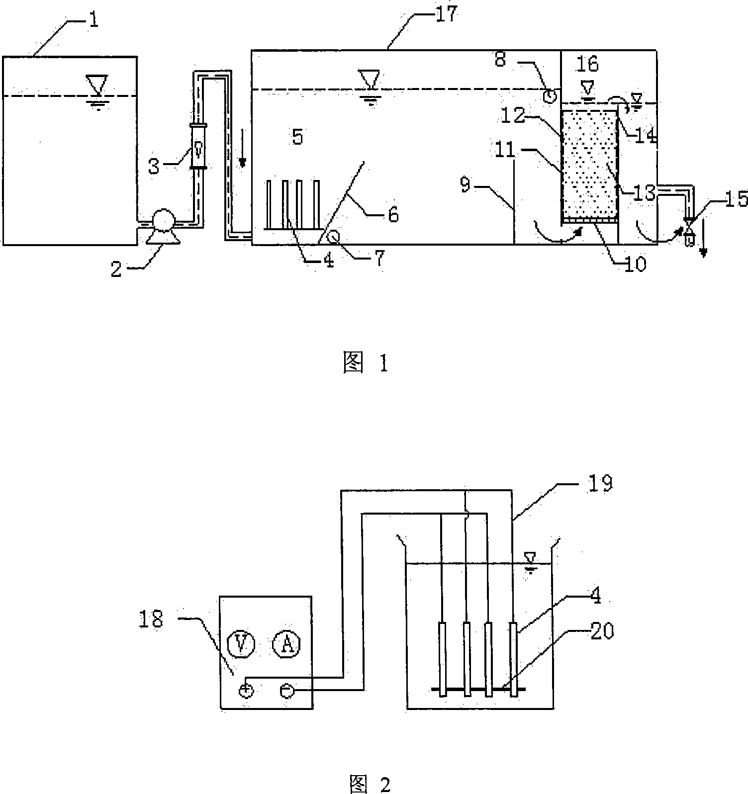
[0022] The oil field waste water in the waste water pool 1 enters the electrical floating area 5 through the water inlet pump 2, and the flow meter 3 measures the water inlet flow. The voltage and current of the electrode plate 4 is controlled by a DC stabilized power supply 18, thereby controlling the number and size of bubbles generated by electrolytic air flotation. The electrode plate 4 is fixed on the container wall with an insulating material 20, and the distance between the electrode plates is 1-2 cm. Electrolytic air flotation produces a large number of micro-bubbles, and the slick oil, most of the dispersed oil and part of the emulsified oil in the wastewater float up with the micro-bubbles, adhere to the micro-bubbles and are brought to the water surface, and the slick oil residue and sludge enter the oil collection pipe 8. After the waste water passes through the deflector sloping plate 6 at 45-60° to the horizontal plane, it crosses the baffle plate 9, passes throug...


PUM

PropertyMeasurementUnit
particle diameteraaaaaaaaaa

Abstract

A device used for treating oil field waste water is characterized of including a water inlet area, a reacting area and a water outlet area. The water inlet area comprises a waste water tank, a water inlet pump and a flowmeter; the water inlet pump is arranged at the outlet of the waste water tank and the flowmeter is arranged on the water inlet pipeline, the reacting area and a water outlet area are located inside the reacting groove, the reacting area is divided into a electrical floating region and a modified magnetic particle adsorption filtration region, wherein the electrical floating region comprises an electric plate the bottom of which is fixed on the device wall by insulation material, a guide flow inclined plate at a dip angle of 45 DEG-60 DEG with the level surface, a perforated pipe which is located on the bottom side of the guide flow inclined plate, a baffle plate located at the bottom and a oil collecting pipe. The modified magnetic particle adsorption filtration region includes a porous plate, a separating plate and modified magnetic particles, wherein the modified magnetic particles are placed in an iron frame. The water outlet area is located on the opposite side of the water inlet area. The disposal unit of the invention is small and compact, the electric devices are less, the power consumption is low and direct current is employed, thereby having low cost working, convenient operation, automatic control and better operability for utilization of actual project.

Description

technical field [0001] The waste water treatment device involved in the present invention particularly refers to a device for treating oil field waste water. Background technique [0002] Most domestic oilfields use oil separation (removal of suspended oil), coagulation air flotation (removal of emulsified oil), filtration, supplemented by biochemical treatment (removal of dissolved oil and most of the organic matter). " process, its treatment process requires a large area, and the oil removal efficiency is not high, especially for the emulsified oil. The long-term water quality compliance rate of each oilfield is low, and a series of problems caused by it restrict the development of the oilfield. [0003] Oilfield wastewater has a very high degree of mineralization (that is, Cl - High content), so the conductivity is high, which meets the conditions required for electrolysis. When using electric floatation treatment, there is no need for a large amount of chemicals to adj...

Claims


Application Information

Patent Timeline
Patent Type & Authority Applications(China)
IPC IPC(8): C02F9/06C02F1/461C02F1/28C02F103/10
Inventor 王利平陈毅忠胡原君薛春阳
Owner 溧阳常大技术转移中心有限公司
Learn More