High pressure underground gas well shaft fixing method

A fixing method and technology for gas storage wells, which are used in wellbore lining, shaft equipment, earth-moving drilling, etc., can solve problems such as threats to the safety of facilities and staff, inability to pour cement slurry, and impact on service life, and promote perfusion and filling. Effect, reliable installation and fixing method, prolonging service life effect

Active Publication Date: 2008-07-09
SICHUAN PETROLEUM & NATURAL GAS SCI & TECH CORP
View PDF1 Cites 14 Cited by
  • Summary
  • Abstract
  • Description
  • Claims
  • Application Information

AI Technical Summary

Problems solved by technology

Although this method overcomes the traditional top-down pouring of cement slurry, the downward pouring depth of cement slurry is shallow, the air and groundwater in the foundation well cannot be discharged, and the lower part and bottom of the wellbore body are difficult to fix; The verticality of the well hole opened is poor, the well wall is uneven, and the wellbore is rigid, and the grouting hose is easy to be flattened, so that the cement slurry cannot be poured down, which affects the fixing effect. The wellbore is easy to loose during use, which will cause left and right Rotation will cause up and down serial movement, especially when the ambient temperature changes greatly, which not only affects normal use, but also poses threats to the safety of facilities and staff; in addition, if the cement slurry cannot move the wellbore Body coating, the exposed part is also easily corroded, which affects the service life

Method used


Image

  • High pressure underground gas well shaft fixing method

Examples


Embodiment 1

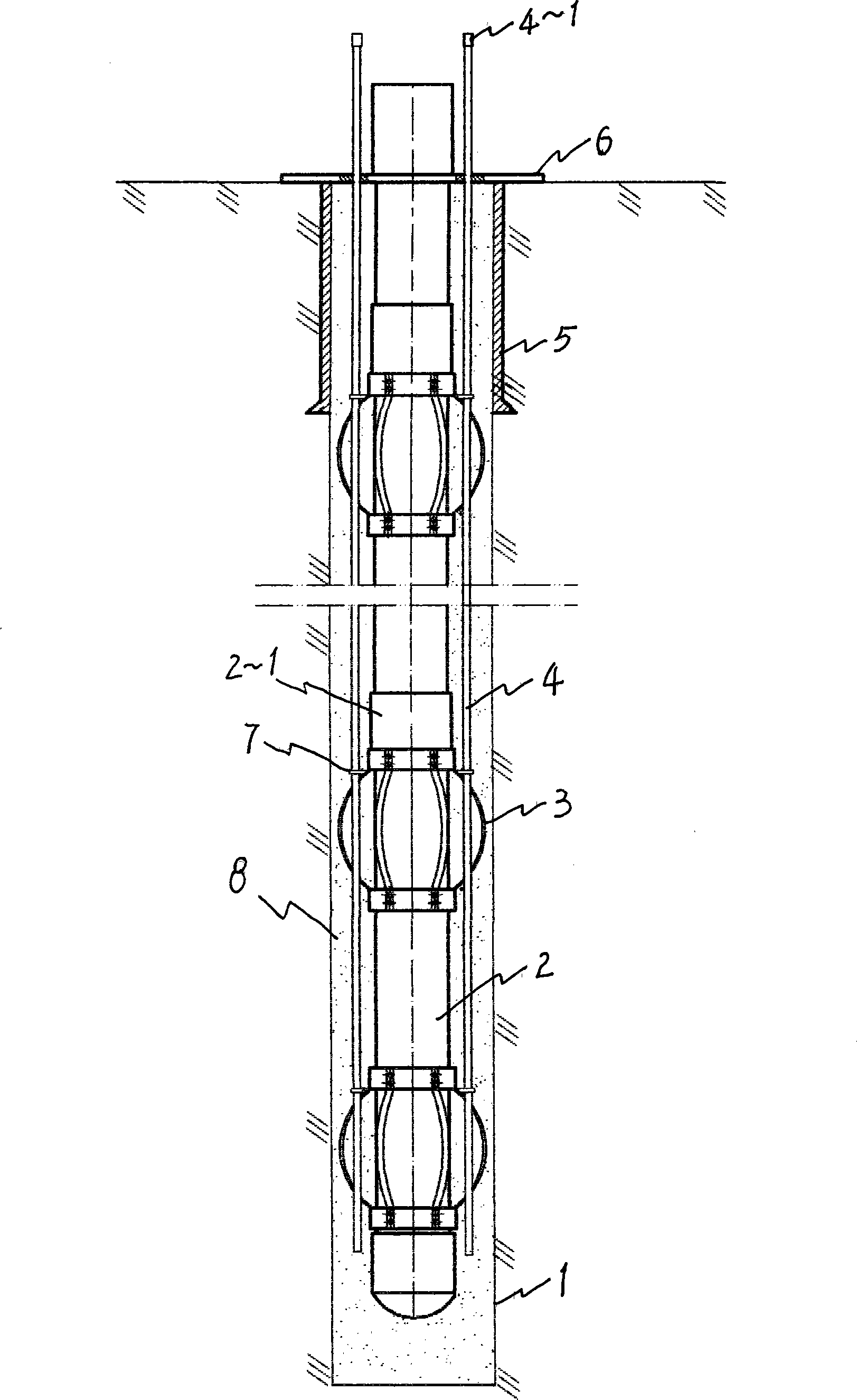
[0011] Embodiment 1: Take the gas storage well that the outer diameter of the gas storage shaft 2 is 7 o'clock (177.8 mm), the total length of the well shaft is 130 m, and the basic well 1 is drilled with a 104 / 5 o'clock (274.32 mm) drill bit as an example:

[0012] A. Lower wellbore and grouting pipe: set a centralizer 3 with an outer diameter of φ268mm and a height of 200mm at each connecting sleeve 2-1 on the wellbore 2, and a high-pressure water injection pipe with a diameter of φ40mm for fire protection in this embodiment. , set 3 pieces at intervals of 120° and fix them with the wellbore 2 through the fixed rings 4-2; The upper part of the pipe 4 is fixed on the surface conduit 5;

[0013] B. Injecting cement slurry: Fill the wellbore with clean water, then connect the three grouting pipes 4 to the mud pumps with output pressures of 3.5Mpa, 6Mpa and 8.5Mpa respectively, then start the mud pump, and use oil well cement according to the conventional method The prepared de...

Embodiment 2

[0015] The wellbore 2 of the gas storage well, the foundation well 1, and the centralizers 3 in this embodiment are the same as in the embodiment 1; the grouting pipe 4 adopts a steel pipe with an outer diameter of φ40mm, two symmetrically arranged and fixed to the wellbore 2 through the fixing rings 4-2, and the two The inlet ends of the grouting pipes 4 are respectively connected to the mud pumps of 5Mpa and 8Mpa; the rest are also the same as in Embodiment 1.


PUM


Abstract

The invention belongs to a method for fixing a high pressure underground gas storage well casing. The method comprises the following steps: a well casing with a centralizer and a plurality of grout pipes are sunk into a basic well; the grout pipes simultaneously inject grout into the basic well at different pressure within the pressure range from 3MPa to 10MPa until the grout overflows. As the centralizer is added on the shell of the well casing and a plurality of pipes are adopted to inject grout at different pressure at the same time, the well casing can be ensured to be arranged at the central position of the basic well while grout of different pressure is injected into the well at the same time. The grout is stirred under the action of the pressure difference; and the injection and filling effect is effectively promoted. The invention has the characteristics of that the installation and fixation method is reliable, the well casing and the wall of the basic well are connected firmly with excellent entirety, the well casing does not loose when in use, the use security of the gas storage well is effectively improved, the performance life is long, etc. The invention overwhelms the defects of the grouting fixation process in the background technology, such as poor reliability and security, likelihood of loosing when in use, etc.

Description

technical field [0001] The invention belongs to a method for fixing shafts of fuel gas underground gas storage wells, in particular to a method for fixing and installing the shafts of high-pressure natural gas underground gas storage wells in foundation wells. Background technique [0002] In the patent document with the notification number CN1384308A and titled "Fixing Method of Underground Gas Storage Well Shaft", it is disclosed that a hose is sunk from one side of the wellbore along the wall of the foundation wellbore, and grouting from the bottom of the wellbore to fix the wellbore. method. Although this method overcomes the traditional top-down pouring of cement slurry, the downward pouring depth of cement slurry is shallow, the air and groundwater in the foundation well cannot be discharged, and the lower part and bottom of the wellbore body are difficult to fix; The verticality of the well hole opened is poor, the well wall is uneven, and the wellbore is rigid, and ...

Claims


Application Information

Patent Timeline
Patent Type & Authority Applications(China)
IPC IPC(8): E21D5/04B65G5/00
Inventor 陈立峰
Owner SICHUAN PETROLEUM & NATURAL GAS SCI & TECH CORP
Why Eureka
Try Eureka