

Heat pump drier
A technology of heat pump drying and drying chamber, which is used in heat pump, drying gas arrangement, drying and other directions
- Summary
- Abstract
- Description
- Claims
- Application Information
AI Technical Summary
Problems solved by technology
Method used
Image

Examples
Embodiment Construction
[0009] Below with Chinese cabbage seed drying as specific embodiment, content of the present invention is further described:
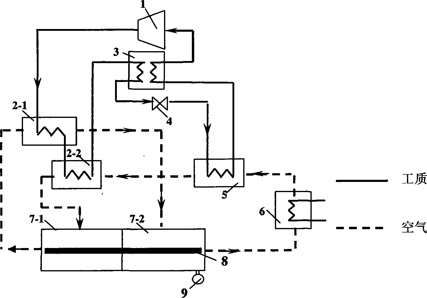
[0010] The dried material cabbage seeds are placed on the conveyor belt in the drying chamber. The initial moisture content of the cabbage seeds is 30%, and they are dried and dehydrated to a moisture content of 5%.
[0011] After compressor 1 is turned on, the CO 2 The working medium is compressed by the compressor 1 into a high-temperature and high-pressure working medium with a pressure of 9 MPa. After the temperature is 75°C, it enters the air source gas cooler 2-1 for the first cooling down to 45°C; at the same time, the temperature is 30°C and the humidity is 80%. The air is heated to a temperature of 45°C, the humidity drops to 35%, and the CO 2 After exchanging heat with the air, the working fluid enters the second air source gas cooler 2-2 for the second cooling down to 25°C. At the same time, the air with a temperature of 20°C and a humidity...
PUM
 Abstract
Description
Claims
Application Information