Pressurized magnetorheological fluid dampers

A magneto-rheological damper and magneto-rheological fluid technology, applied in the direction of shock absorbers, shock absorbers, railway car body parts, etc., can solve the problems of minimizing, not explaining cavitation, etc., and achieve the effect of improving performance

Active Publication Date: 2008-07-09
THE CHINESE UNIVERSITY OF HONG KONG
View PDF3 Cites 20 Cited by
  • Summary
  • Abstract
  • Description
  • Claims
  • Application Information

AI Technical Summary

Problems solved by technology

Although Carlson mentions that the battery pressurizes the MR fluid to minimize any cavitation, Carlson does not explain how to minimize cavitation

Method used


Image

  • Pressurized magnetorheological fluid dampers
  • Pressurized magnetorheological fluid dampers
  • Pressurized magnetorheological fluid dampers

Examples


Embodiment Construction

[0026] Some exemplary embodiments of the present invention will now be described with reference to the drawings, wherein like numerals refer to like parts.

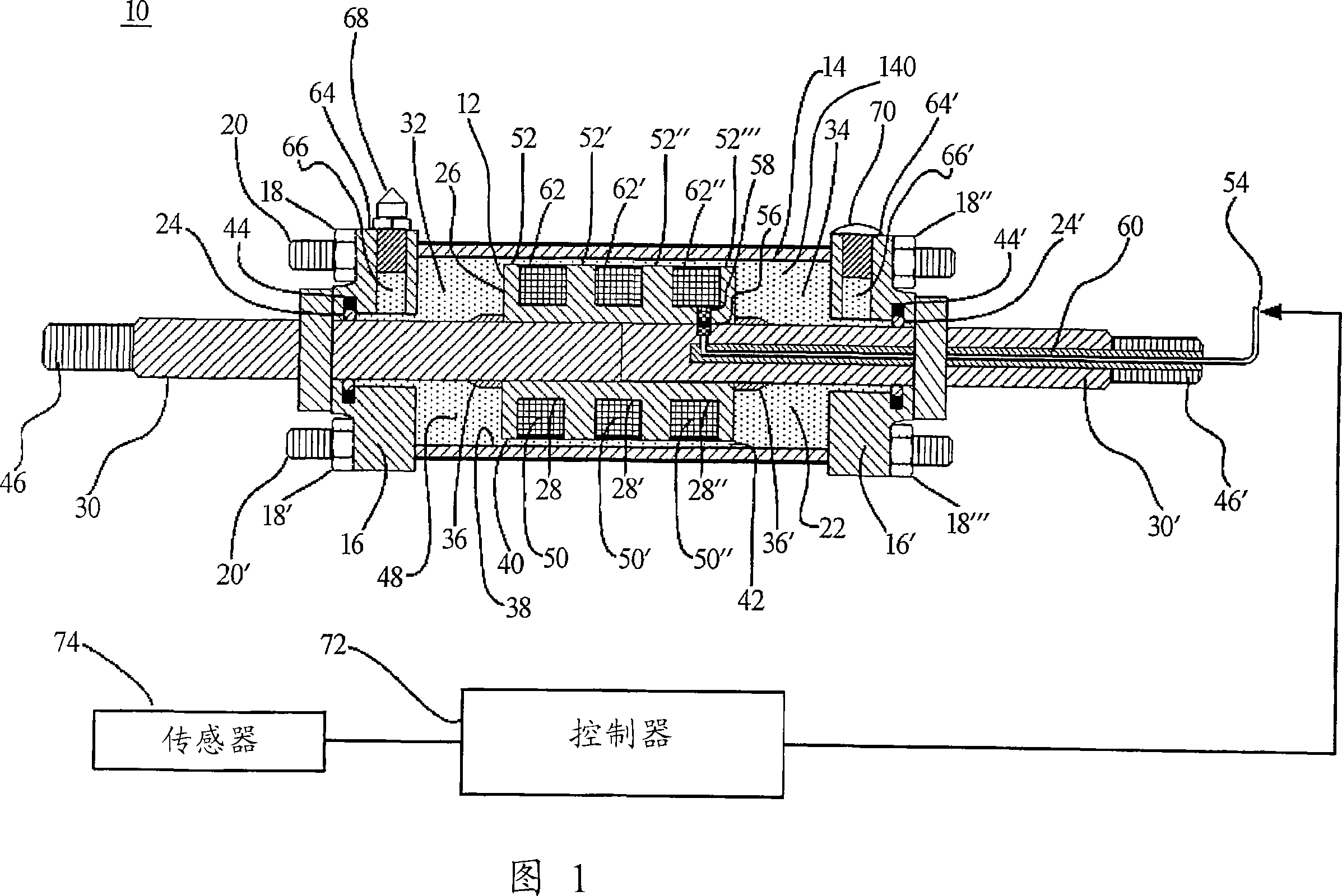
[0027] Fig. 1 shows an MR device 10, in particular an MR damper, according to an exemplary embodiment of the present invention.

[0028] The MR damper 10 includes a housing or body 14 typically made of a soft magnetic material such as mild steel. In this embodiment, the housing 14 provides a cylindrical cavity 140 .

[0029] The housing 14 is closed at its ends by two covers 16 and 16' which are fastened by tie rod nuts 18, 18', 18" and 18'' on the tie rods 20 and 20' (in this embodiment , there are a total of 8 tie nuts and 4 tie rods, which are not fully shown in Figure 1). They are fitted together to form a partially closed compartment.

[0030] Two circular holes 24 and 24' are formed in the center of the rod caps 16 and 16' respectively. Bores 24 and 24' accommodate two axially slidable piston rods 30 and 30' resp...


PUM


Abstract

A magnetorheological (MR) fluid device including a pressurized MR liquid with an improved performance is provided. Also provided is a method for minimizing cavitation of a common magnetorheological device, comprising providing an MR fluid within the device with a pressure of at least 100psi. The device as provided minimizes cavitation in the device, and can be broadly used in the railway vehicle suspension system with excellent performance.

Description

[0001] This application claims priority to US Provisional Patent Application Serial No. 60 / 703,428, filed July 29, 2005, the entire contents of which are expressly incorporated herein by reference. technical field [0002] The present invention relates to magnetorheological (MR) fluid devices, and more particularly to magnetorheological (MR) fluid dampers with pressurized MR fluid. Background technique [0003] Magnetorheological fluid devices using MR fluid as the working medium to generate controllable viscous damping force are promising for shock absorption. Compared with traditional semi-active devices (such as variable orifice dampers), MR fluid dampers respond quickly and have fewer moving parts (only a piston assembly), which makes MR fluid dampers simple and reliable. [0004] The good adaptability of MR devices also enables novel applications in terms of promising flexibility. Various MR devices have been developed for different applications, such as MR rotary devi...

Claims


Application Information

Patent Timeline
Patent Type & Authority Applications(China)
IPC IPC(8): F16F9/53F16F9/32B60G17/08B60G99/00
CPCF16F9/535B60G17/0152B60G2300/10B60G2300/45B61F5/144B61F5/245F16F9/53B60G17/08F16F9/32
Inventor 刘耀基廖维新
Owner THE CHINESE UNIVERSITY OF HONG KONG
Why Eureka
Try Eureka