Non-air throttle engine and method for controlling power and maintaining constant pressure and contractive pressure and evading explosion

A technology of engine and compression pressure, which is applied in the direction of engine control, electrical control, engine ignition, etc., and can solve problems such as inability to obtain compression pressure, poor adjustment of compression pressure, and inability to maintain optimal working conditions

Inactive Publication Date: 2008-07-16
兰永柱
View PDF2 Cites 1 Cited by
  • Summary
  • Abstract
  • Description
  • Claims
  • Application Information

AI Technical Summary

Problems solved by technology

[0003] Furthermore, the density of the air to a certain extent (related to temperature) can be reflected by the compression pressure value, the compression pressure is crucial to the performance of the engine, and the different (ideal) compression pressures of various working conditions are the efforts to improve the performance of the engine Direction, the single methods currently used such as variable compression ratio technology, variable gas distribution technology, and throttle control are not effective in adjusting the compression pressure, especially in the face of various working conditions. This single method cannot obtain For the problem of different (ideal) compression pressures in various working conditions, the engine can only obtain a point of the best working condition, and cannot obtain the line to maintain the best workin

Method used


Image

  • Non-air throttle engine and method for controlling power and maintaining constant pressure and contractive pressure and evading explosion
  • Non-air throttle engine and method for controlling power and maintaining constant pressure and contractive pressure and evading explosion
  • Non-air throttle engine and method for controlling power and maintaining constant pressure and contractive pressure and evading explosion

Examples


Embodiment approach

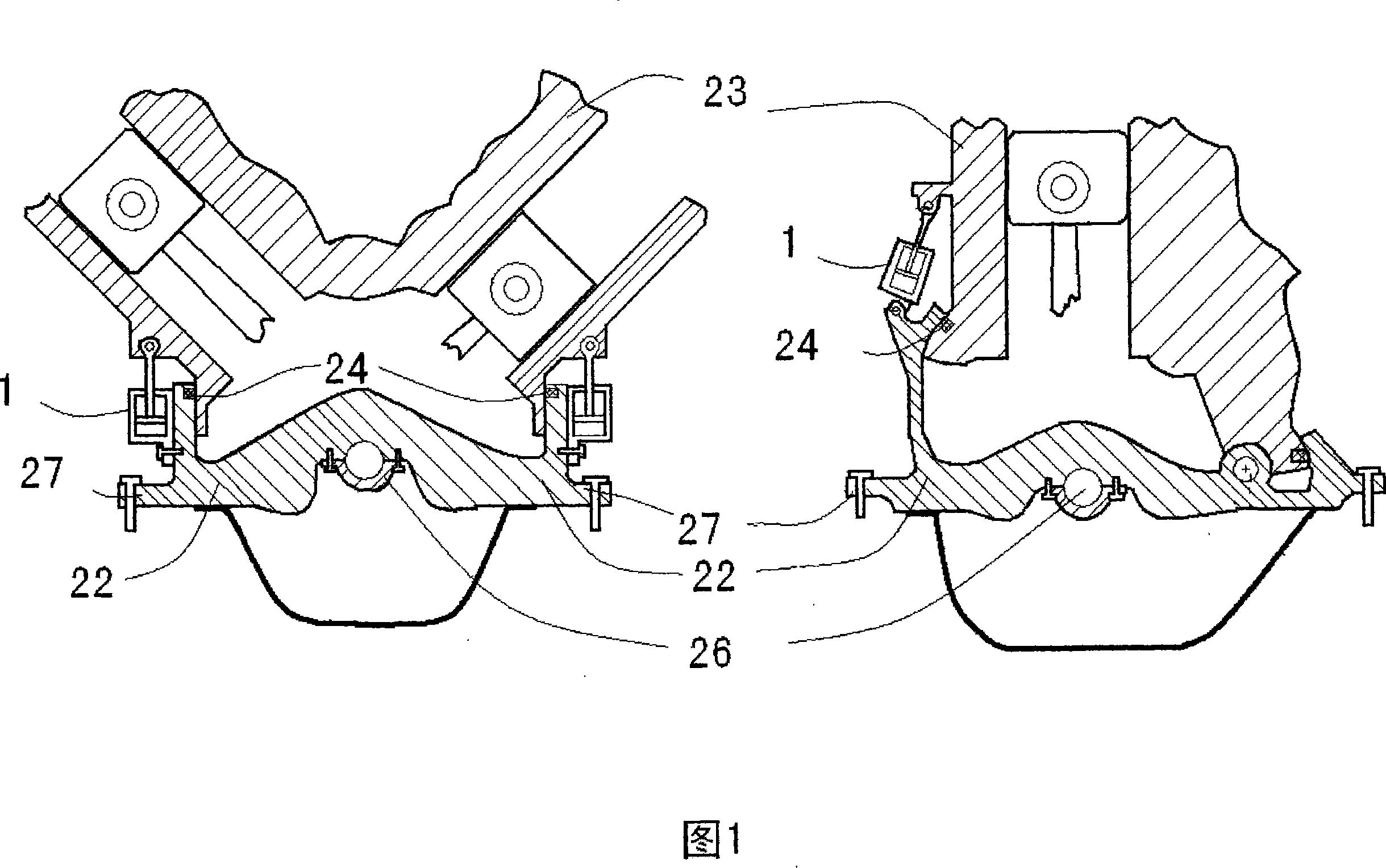
[0069] The engine consists of an electronic control system, a compression pressure adjustment system, an upper and lower cylinder moving device, a special electromagnetic valve (including an electromagnetic hydraulic valve) that generates an exhalation (expiration) stroke, an air distribution system for the control system, and other necessary systems. composition. A preferred example is: the executive mechanism of the upper and lower cylinder moving device is controlled by the regulation pressure instruction of the compression pressure adjustment system, and its electromagnetic valve is controlled by the accelerator pedal signal. Another implementation of the second preferred embodiment is: the actuator of the upper and lower cylinder moving device is controlled by the accelerator pedal signal, and the combined cam mechanism is controlled by the regulation pressure instruction of the compression pressure adjustment system.

[0070] The third preferred embodiment of the recipro...


PUM


Abstract

A combustion volume technique and a control inflation quantity technique can be synchronously executed and controlled so as to gain a most suitable compression pressure which aims at avoiding detonation, optimum operation and fuel adaptation under full working condition by an upper and lower cylinder moving device which is controlled by a servo system, a combination camshaft device, a built-in device, a special electricity removal excitation valve control system, and a compression pressure arrangement and adjustment system which is based on the previous devices. The best working point of an engine is elongated to the line of all power lines of full working conditions, and the engine always keeps the best working state under the full working condition, has more powerful power and saves the energy and protects the environment more. By adopting the technique, the invention gains a method which leads a reciprocating engine to generate an expiration (aspiration) stroke and controls the power thereout. The invention provides the method which leads the engine to keep constant compression pressure under full working condition and restrains and avoids the occurrence of detonation and deflagration by reducing the compression pressure.

Description

Technical field: [0001] This invention relates to reciprocating engines. Background technique: [0002] I have an original (invention) patent (patent number: 200710057139.X) that I have applied for. This patent uses the mechanical displacement of the mechanical controller (accelerator pedal) as the parent command, and adopts a synchronous linkage positioning displacement device and an upper and lower cylinder moving device. , Combined camshaft mechanism, constant air-fuel ratio oil supply system four independent technologies, and the engine implementing the four inventions of the patent at the same time has five strokes of suction, exhalation (exhalation), compression, explosion, and exhaust. The combined camshaft mechanism in this patent has an anti-rotational displacement connector, wherein the actuator drives the cam mandrel, and the cam mandrel drives the cam lobe, which can cause the intake valve to be closed late at the end of the suction stroke, and the piston goes up...

Claims


Application Information

Patent Timeline
IPC IPC(8): F02D15/04F01L9/02F01L9/04F02D45/00F02D41/04F02D41/26F02P5/152F01L9/10F01L9/20
Inventor 兰永柱
Owner 兰永柱
Why Eureka
Try Eureka