
Submarine manipulator shoulder joint

An underwater manipulator and shoulder joint technology, which is applied to manipulators, underwater operation equipment, ships, etc., can solve the problems of unfavorable hydraulic oil pipe pipeline layout, large volume of manipulator, and non-compact structure, and achieves favorable pipeline layout and rotation. Flexible, compact effects

Inactive Publication Date: 2008-07-23
HARBIN ENG UNIV
View PDF1 Cites 12 Cited by
  • Summary
  • Abstract
  • Description
  • Claims
  • Application Information

AI Technical Summary

Problems solved by technology

[0005] There are also many related reports on the shoulder joint of underwater manipulators, for example: "Six-function underwater manipulator variable structure control method and application research" (Master's thesis of Shenyang Institute of Automation, Chinese Academy of Sciences, 2002), "Monitoring underwater manipulator and related The underwater manipulator mentioned in "Research on Technology" (Master's Thesis of Shenyang Institute of Automation, Chinese Academy of Sciences, 2001), the shoulder rotation is realized by the hydraulic cylinder installed in the base, and the shoulder swing is realized by the hydraulic cylinder installed in the shoulder cavity. Realization, the distance between the shoulder shaft and the shoulder swing shaft is relatively long, the structure is not compact, and it is not conducive to the layout of hydraulic oil pipes, resulting in defects such as large volume and heavy weight of the entire manipulator; "5 degrees of freedom autonomous underwater manipulator The 5-DOF autonomous underwater manipulator mentioned in "Research and Development" (China Mechanical Engineering, 2001, 12 Supplement: 16-18), the underwater manipulator shoulder has only one rotational degree of freedom; the underwater manipulator recorded in US Patent US4648782 The shoulder has only one pitching degree of freedom, and the shoulder is directly installed on the base; the shoulder has only one pitching degree of freedom
[0006] Underwater manipulators are required to have the characteristics of light weight, small size, compact structure, flexible manipulation, and large range of motion. Obviously, the existing design schemes for shoulder joints of underwater manipulators cannot meet this requirement.

Method used


Image

  • Submarine manipulator shoulder joint

Examples


Embodiment Construction

[0016] The present invention is described in more detail below in conjunction with accompanying drawing example:

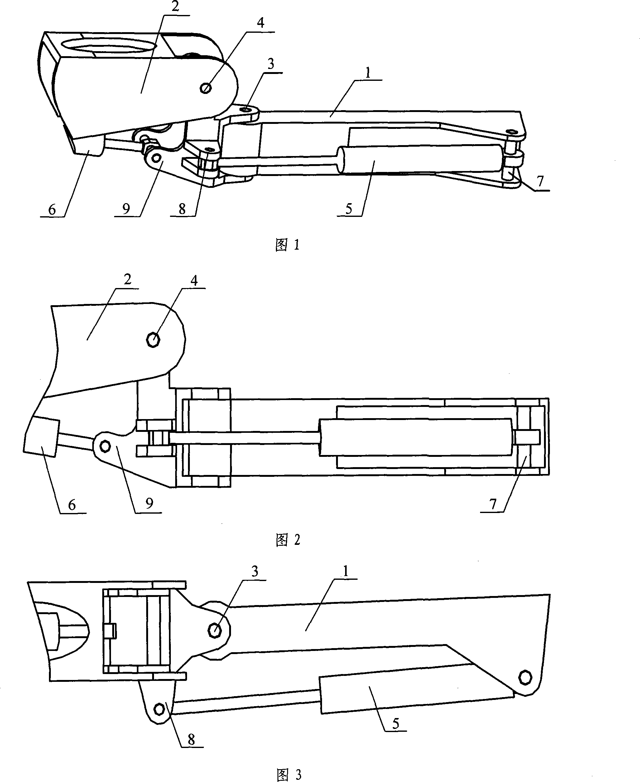
[0017] Combined with Figures 1-3, the shoulder joint of the underwater manipulator is connected by a base frame 1, an upper arm 2, a yaw shaft 3, a pitch shaft 4, a hydraulic cylinder 5, a hydraulic cylinder 6, a hydraulic cylinder bottom connecting shaft 7, and a hydraulic cylinder piston rod. The hinge seat 8 and the hydraulic cylinder piston rod joint hinge seat 9 are composed of the base frame 1 and the shoulder joint through the yaw shaft 3, and the upper arm 2 is connected with the shoulder joint through the pitch shaft 4; the bottom of the hydraulic cylinder 5 is connected through the bottom of the hydraulic cylinder. The end connecting shaft 7 is connected with the base frame 1, the piston rod end of the hydraulic cylinder 5 is connected with the shoulder joint through the hydraulic cylinder piston rod connecting hinge seat 8; the piston rod end of the hydr...


PUM


Abstract

The invention provides an underwater manipulator shoulder joint, consisting of a foundation frame, an upper arm, a yaw rotating shaft, a pitching rotating shaft, a hydraulic cylinder, a coupling spindle at the bottom of the hydraulic cylinder and a piston rod hinge base of the hydraulic cylinder; wherein, the foundation frame is linked to a shoulder joint through the yaw rotating shaft; the upper arm is linked to the shoulder joint through the pitching rotating shaft; the shoulder joint is provided with two piston rod hinge bases of the hydraulic cylinder which are respectively linked to two hydraulic cylinders; wherein, one hydraulic cylinder is arranged on the foundation frame, and the other hydraulic cylinder is arranged in a cavity of the upper arm. The invention is used for the underwater robot and has the advantages of simple structure, light weight, and flexible rotation. The invention realizes the motion of two DOFs rotation of the shoulder joint; furthermore, the distance between the two rotating shafts is extremely close, thus leading the structure to be compact.

Description

(1) Technical field [0001] The invention relates to an underwater robot technology, in particular to an underwater manipulator shoulder joint structure for an underwater robot. (2) Background technology [0002] The ocean is rich in biological resources, mineral resources and a large amount of energy such as oil, coal and natural gas. With the continuous shortage of resources on land, it is an inevitable trend for human beings to go to the sea. At the same time, the ocean determines the climate of various regions of the earth, and the ecological environment of the ocean is a barometer of the ecological environment of the earth. Therefore, it is necessary to monitor the environment of all parts of the ocean, including places that people cannot reach. [0003] At present, many countries in the world have realized the importance of using and developing the ocean, and have invested a lot of money, manpower, and material resources in research work in this area. The status of ma...

Claims


Application Information

Patent Timeline
IPC IPC(8): B25J17/00B63C11/52
Inventor 姚建均王立权王茁王成军王才东张存良
Owner HARBIN ENG UNIV
Learn More