
Photosensitive gap material for liquid crystal display device, manufacturing method thereof and liquid crystal display device

A technology for a liquid crystal display and a manufacturing method, applied in the directions of photosensitive materials for optomechanical equipment, photolithographic process exposure devices, static indicators, etc.

Inactive Publication Date: 2008-07-23
FUJIFILM CORP
View PDF21 Cites 1 Cited by
  • Summary
  • Abstract
  • Description
  • Claims
  • Application Information

AI Technical Summary

Problems solved by technology

In order to achieve this requirement, although the cross-linking reaction rate of monomers can be increased and the deformation recovery rate can be increased to a certain extent, the improvement effect tends to reach its peak, and further improvement is required.

Method used


Image

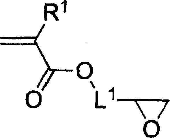
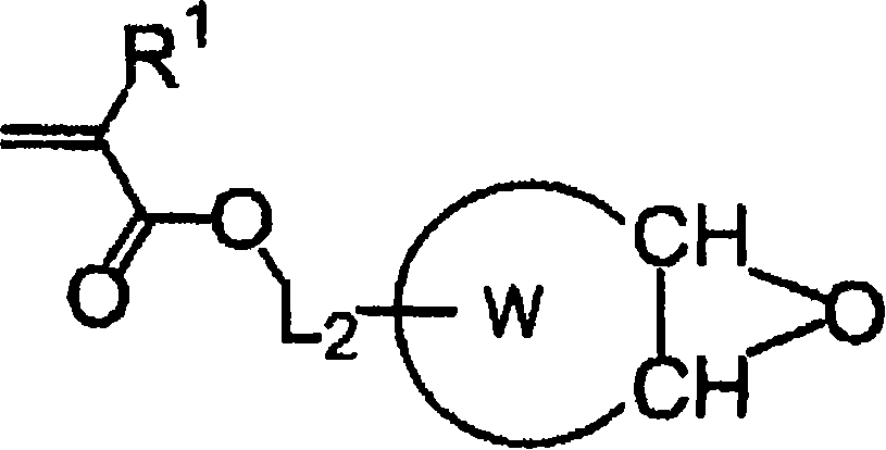
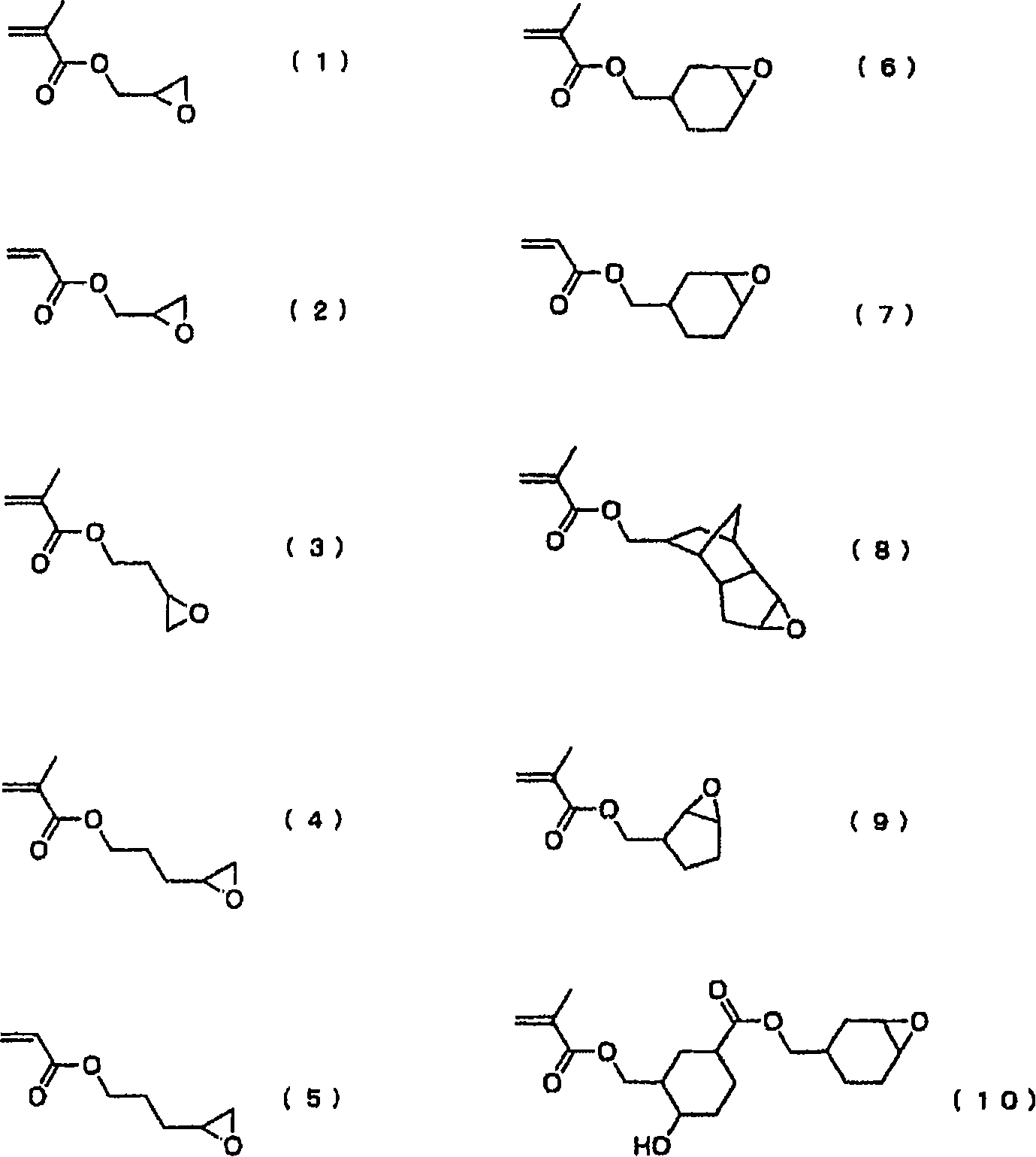
  • Photosensitive gap material for liquid crystal display device, manufacturing method thereof and liquid crystal display device
  • Photosensitive gap material for liquid crystal display device, manufacturing method thereof and liquid crystal display device
  • Photosensitive gap material for liquid crystal display device, manufacturing method thereof and liquid crystal display device

Examples


Embodiment

[0155] Hereinafter, the present invention will be described in more detail using examples, but the present invention is not limited by the following examples within the range not exceeding the gist. In addition, unless otherwise specified, "part" and "%" are weight standards.

Synthetic example 1

[0157] Add 5.11 parts of 1-methoxy-2-propanol and 5.11 parts of 1-methoxy-2-propyl acetate to the reaction vessel in advance, raise the temperature to 90°C, and under nitrogen atmosphere, the reaction vessel at 90°C 5.10 parts of styrene, 9.84 parts of methacrylic acid, 1 part of an azo-based polymerization initiator (manufactured by Wako Pure Chemical Industries, Ltd., V-601) and 5.11 parts of 1-methoxy-2-propanol were instilled over 2 hours. and a mixed solution consisting of 5.11 parts of 1-methoxy-2-propyl acetate. After dripping, it was allowed to react for 4 hours to obtain an acrylic resin solution.

[0158]Next, 0.036 parts of hydroquinone monomethyl ether and 0.082 parts of tetraethylammonium bromide were added to the acrylic resin solution, and then 9.28 parts of glycidyl methacrylate was dripped over 2 hours. After dripping, it was reacted at 90° C. for 4 hours while blowing in air, and then a solvent was added to make the solid content concentration 45%, thereby p...

Synthetic example 2

[0162] Add 13.56 parts of 1-methoxy-2-propanol to the reaction vessel in advance, raise the temperature to 90°C, and drip 8.24 parts of cyclohexyl methacrylate, A mixed solution consisting of 9.84 parts of methacrylic acid, 1 part of an azo polymerization initiator (manufactured by Wako Pure Chemical Industries, Ltd., V-601), and 13.56 parts of 1-methoxy-2-propanol. After dripping, it was allowed to react for 4 hours to obtain an acrylic resin solution.

[0163] Next, 0.0415 parts of hydroquinone monomethyl ether and 0.068 parts of tetraethylammonium bromide were added to the acrylic resin solution, and then 9.28 parts of glycidyl methacrylate was dripped over 2 hours. After dripping, react at 90° C. for 4 hours while blowing in air, and then add a solvent so that the solid content concentration becomes 45%, thereby preparing a resin solution represented by the compound P-10 having an unsaturated group ( Solid content acid value: 100 mgKOH / g, Mw: 18,000, 45% solution of 1-met...


PUM

PropertyMeasurementUnit
glass transition temperatureaaaaaaaaaa
particle sizeaaaaaaaaaa
thicknessaaaaaaaaaa

Abstract

The invention provides a light-sensitive clearance material for eliminating the inhomogeneous display on the liquid crystal display device with high reversed deformation property and manufacturing method thereof and a liquid crystal display device for preventing the inhomogeneous display and displaying the image of high image quality. The manufacturing method thereof comprises steps of: forming the resin layer, exposing, developing and post-developing, characterized in that the exposure of one surface of the supporter with the light-sensitive resin layer is 5 times higher than the threshold exposure required for solidifying the light-sensitive resin layer during the step of post-exposing and the exposure of the opposite surface to the surface of the supporter with the light-sensitive resin layer is below 20mJ / cm2.

Description

technical field [0001] The present invention relates to a method for producing a photosensitive spacer for a liquid crystal display, which is preferable in the production of a spacer for a display device in which fluctuations in the thickness of cells constituting a liquid crystal cell tend to cause display unevenness, and a photosensitive spacer for a liquid crystal display produced by the method and A liquid crystal display device including the photosensitive spacer for a liquid crystal display. Background technique [0002] Conventionally, liquid crystal display devices have been widely used as display devices for displaying images with high image quality. In a liquid crystal display device, a liquid crystal layer capable of displaying an image with a predetermined orientation is usually disposed between a pair of substrates. Maintaining the distance between the substrates uniformly, that is, the thickness of the liquid crystal layer is one of the factors that determine i...

Claims


Application Information

Patent Timeline
Patent Type & Authority Applications(China)
IPC IPC(8): G02F1/1339G03F7/00G03F7/20G03F7/004
CPCG02F1/133512G02F1/13394G09G2320/02G02F1/13398
Inventor 吉成伸一
Owner FUJIFILM CORP
Learn More