Flywheel energy-accumulating type secondary regulation flux coupling system

A technology of secondary adjustment and flywheel energy storage, which is applied in the direction of fluid pressure actuation system components, fluid pressure actuation devices, mechanical equipment, etc., can solve the problems of high system cost, high power density, low energy density, etc., and achieve reduction Cost, reduced installed power, and small effect of temperature

Inactive Publication Date: 2008-07-30
HARBIN INST OF TECH
View PDF1 Cites 28 Cited by
  • Summary
  • Abstract
  • Description
  • Claims
  • Application Information

AI Technical Summary

Problems solved by technology

[0005] In order to solve the problems of large power density, low energy density and high system cost in the existing secondary regulation hydrostatic transmission system using hydraulic accumulator energy storage, the present invention provides a flywheel energy storage type secondary regulation flow coupling system

Method used


Image

  • Flywheel energy-accumulating type secondary regulation flux coupling system

Examples


specific Embodiment approach 1

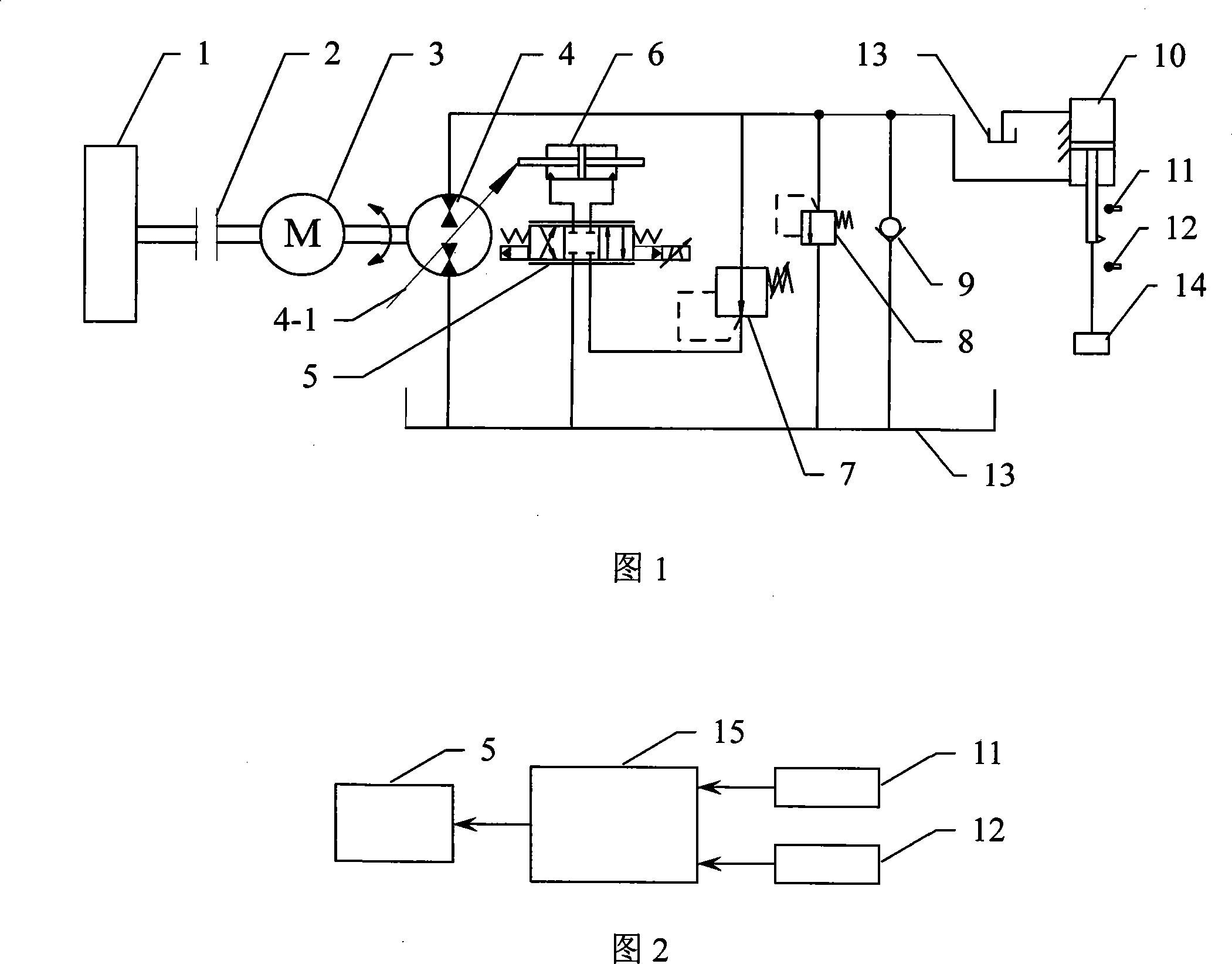
[0010] Specific Embodiment 1: The flywheel energy storage type secondary adjustment flow coupling system of this embodiment consists of a biaxial motor 3, a hydraulic pump / motor 4, an electro-hydraulic control valve 5, a variable cylinder 6, a pressure reducing valve 7, and a hydraulic cylinder 10 , an upper limit sensor 11, a lower limit sensor 12, a fuel tank 13, a controller 15 and a flywheel 1; the drive shaft of the flywheel 1 is fixedly connected to an output shaft of the biaxial motor 3, and the other output shaft of the biaxial motor It is fixedly connected with the transmission shaft of the hydraulic pump / motor 4, the swash plate 4-1 of the hydraulic pump / motor 4 is connected with the piston rod of the variable cylinder 6, and the two oil delivery ports of the variable cylinder 6 are respectively connected with the electro-hydraulic control valve 5 The two oil delivery ports of the electro-hydraulic control valve 5 communicate with the oil outlet of the fuel tank 13 an...

specific Embodiment approach 2

[0016] Embodiment 2: The difference between this embodiment and the flywheel energy storage type secondary regulation flow coupling system described in Embodiment 1 is that it also includes an electromagnetic clutch 2, the drive shaft of the flywheel 1 and the output of the biaxial motor 3 The shafts are connected by electromagnetic clutch 2.

[0017] When the flywheel energy storage type secondary regulation flow coupling system described in this embodiment is working, the initial state of the system is: the hydraulic pump / motor 4 is in the pump mode, the electromagnetic clutch 2 is in the disengaged state, and the biaxial motor 3 is in the Working status, the working process is:

[0018] Driven by a motor, the double-axis motor 3 drives the hydraulic pump / motor 4 to drive the hydraulic cylinder 10 to drive the load 14 to rise;

[0019] Drive / energy storage conversion, when the hydraulic cylinder 10 drives the load 14 up to the position where the upper limit sensor 11 is tri...


PUM


Abstract

The invention discloses a flywheel energy storage type secondary flow regulation coupled system, which relates to a closed loop hydraulic control system, and the invention solves the problems of high power density, low energy density and high cost existing in the existing secondary regulation hydrostatic transmission system which adopts a hydraulic accumulator to store energy. Two output shafts of a double-shaft motor in the system are respectively connected with a drive shaft of the flywheel and a transmission shaft of a hydraulic pump or a motor, and a variable cylinder regulates the working position of a sloping plate of the hydraulic pump or the motor under the control of an electro-hydraulic control valve. An upper limit sensor and a lower limit sensor are respectively fixed at the side face of a piston rod of a hydraulic cylinder to measure the position of the piston rod, and signal output ends of the upper limit sensor and the lower limit sensor are respectively connected with a signal output end of a controller. A control signal output end of the controller is connected with the control signal output end of the electro-hydraulic control valve, and the invention is suitable for industries of oil, mine and engineering plant, etc., especially for the system of frequent reciprocating motion and frequent start-stop.

Description

technical field [0001] The invention relates to a closed-loop hydraulic control system, in particular to a secondary regulating flow coupling system. Background technique [0002] The traditional secondary regulation technology refers to the hydraulic transmission technology that performs closed-loop control on the hydraulic pump / motor without throttling in the constant pressure network. Since the system works in a quasi-constant pressure state, it is also called CPS (Common Pressure System), CPR (Common Pressure Rail), or SCS (Secondary Controlled System), which is actually a pressure coupling system. This technology has attracted more and more attention because of its advantages such as multi-load parallel connection, good control characteristics, and the ability to recover system braking kinetic energy. However, the secondary regulation hydrostatic transmission system working on the constant pressure network also has its disadvantages: the system usually can only be conn...

Claims


Application Information

Patent Timeline
Patent Type & Authority Applications(China)
IPC IPC(8): F15B15/18F15B21/14
Inventor 姜继海刘海昌
Owner HARBIN INST OF TECH
Why Eureka
Try Eureka