

Thermoelectric module and package thereof
A technology of thermoelectric and transducer elements, which is applied in thermoelectric device components, manufacturing/processing of thermoelectric devices, thermoelectric device node lead-out materials, etc., and can solve the problem of wire bonding strength offset, damage, and insufficient thermoelectric transduction modules etc., to achieve the effect of reducing the resistance of wiring, good bonding strength, and excellent wettability
- Summary
- Abstract
- Description
- Claims
- Application Information
AI Technical Summary
Problems solved by technology
Method used
Image

Examples
Embodiment 1
[0151] (Fabrication of thermoelectric transducer elements)
[0152] First, various N-type and P-type thermoelectric materials are fabricated. The production method is: prepare Bi, Te, Sb, Se metal powder with a purity of 99.99% or more and SbI as a dopant for thermoelectric transducer elements 3 Powder and SbBr 3 powder. As an N-type thermoelectric material, Bi 2 Te 2.85 Se 0.15 Based on the composition, the amount of the dopant is adjusted in order to adjust the specific resistance.
[0153] In addition, the P-type uses thermoelectric materials with Bi x Sb 2-x Te 3 As a basis, make x vary from 0.3 to 0.7, and adjust the specific resistance.
[0154] (a) Formation of sintered body
[0155] After the raw materials were weighed to a desired composition, they were filled into a carbon crucible and sealed with a lid. Put it into a quartz tube, perform vacuum replacement, and produce a molten alloy at 800° C. for 5 hours in an argon atmosphere.
[0156] The molten allo...
Embodiment 2
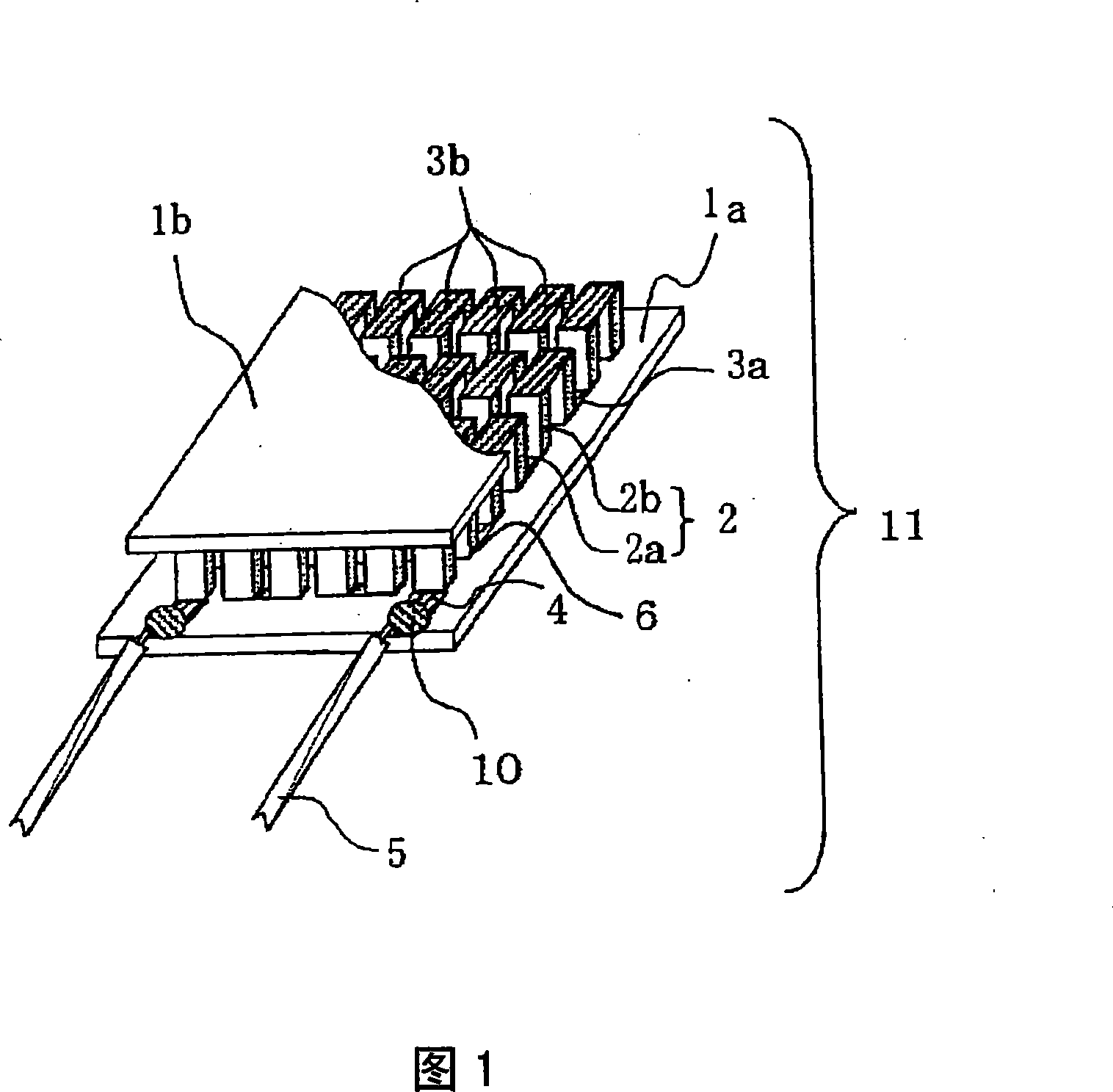
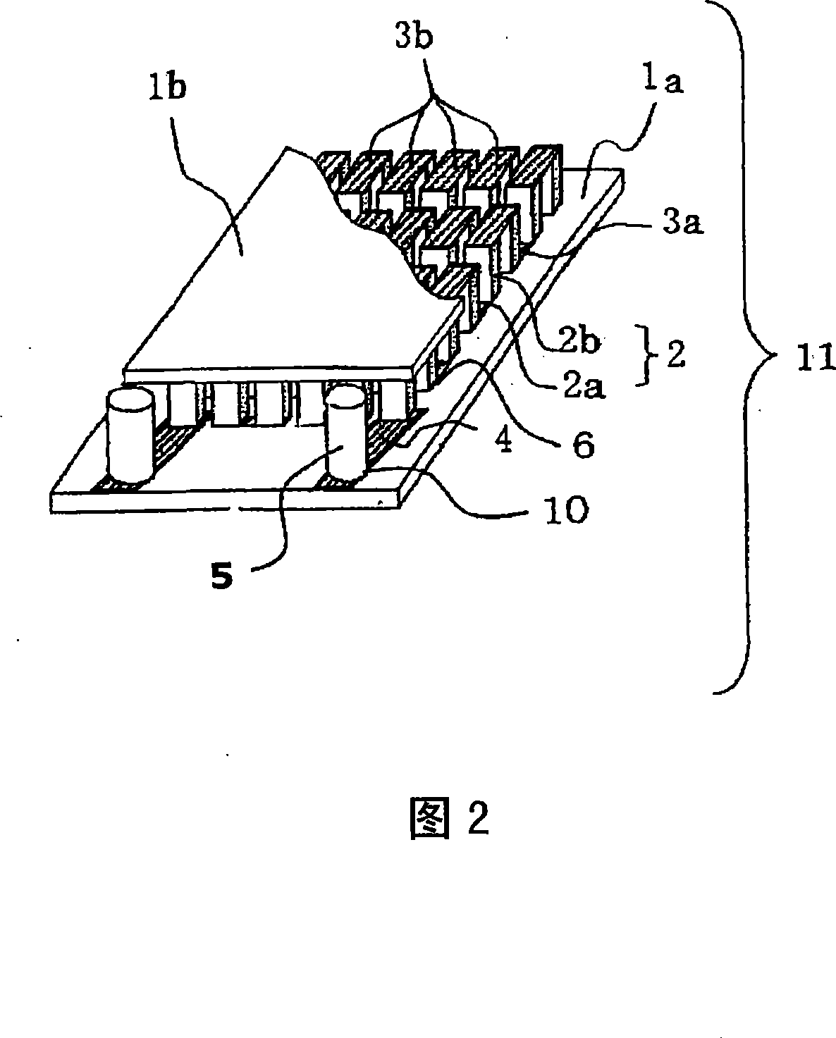
[0189] The initial feedstock was prepared by Bi 2 Te 2.85 Se 0.15 A thermoelectric transducer element 2 composed of a sintered body. The shape is a square prism, and the size is 0.6mm in length, 0.6mm in width, and 1mm in height. In addition, as the support substrate 1, alumina having a size of 6 mm×8 mm was prepared.
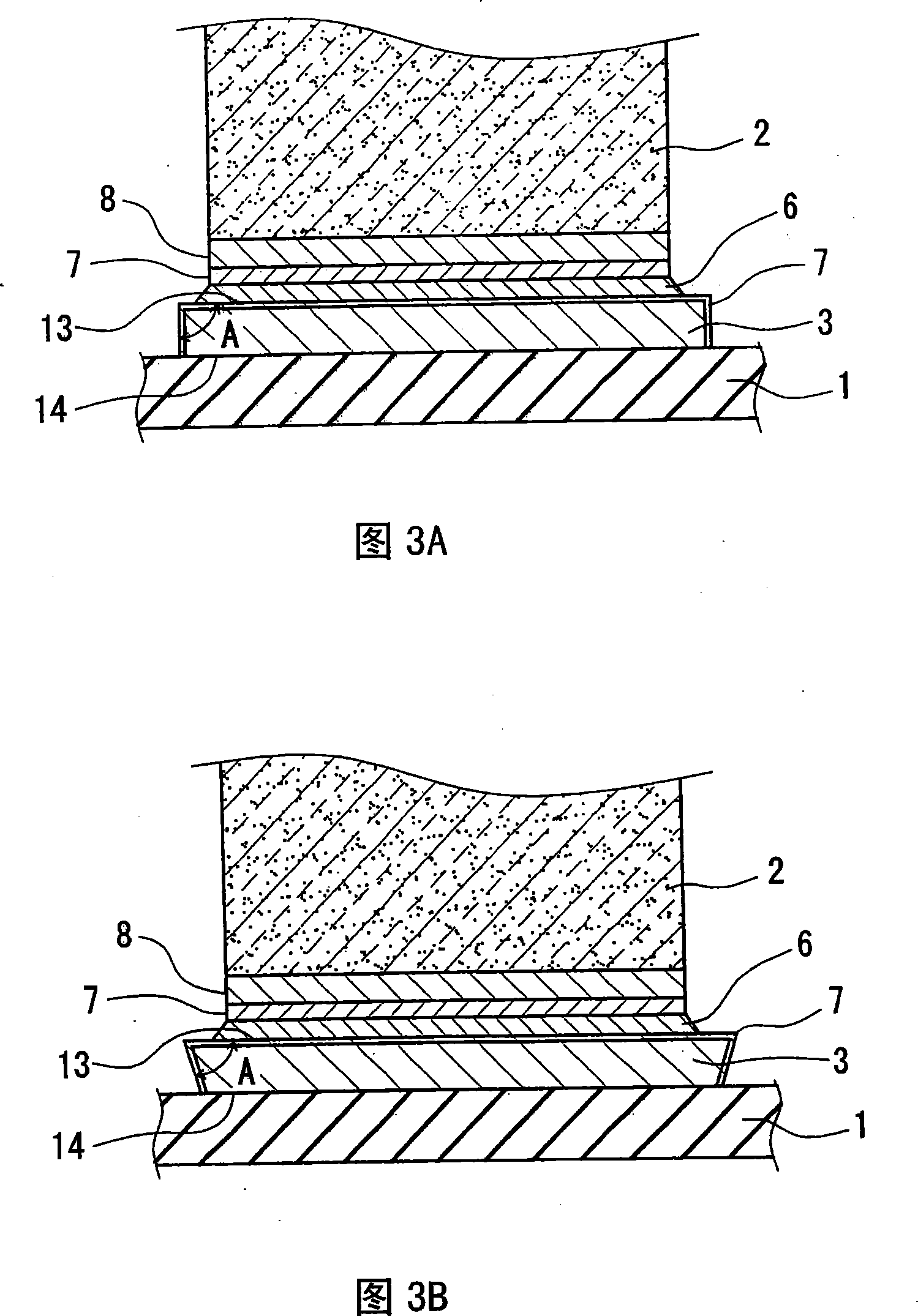
[0190] Cu wiring conductors 3 are formed on the supporting substrate 1 by a plating-etching method. A cover layer 7 of Au is formed on the surface.
[0191] On the wiring conductor 3a of the lower supporting substrate 1a, solder paste composed of solder 6 such as Au-Sn is printed, and the thermoelectric transducer elements 2 are arranged on it, and heated from the reverse side of the lower supporting substrate 1a to fix the thermoelectric element. Transducer element 2. The number of thermoelectric transducer elements 2 is the same number of N-type thermoelectric transducer elements 2a and P-type thermoelectric transducer elements 2b respectively. Similar...
Embodiment 3
[0201] A thermoelectric transducer module was produced in the same manner as in Example 2 except that the composition of the solder for connecting the leads was changed.
[0202] Place the obtained thermoelectric transducer module in a high-temperature atmosphere at 170°C, and measure the resistance change (ΔR) after 100 hours by the AC 4-terminal method. If ΔR exceeds 5%, it is unqualified, that is, ×, and if it is less than 5%, it is qualified. ○.
[0203] [table 3]
[0204] sample
No.
Lead solder composition
Component gas
Porosity (%)
Thermoelectric transducer element
ΔR(%)
Judgment
Sn(wt%)
Other composition (weight%)
P type
N type
1
20
Au
80
2
Bi 0.5 Sb 1.5 Te 2
Bi 2 Te 2.85 Se 0.15
0.2
◎
2
12
Au
88
2
Bi 0.5 Sb 1.5 Te 2
Bi 2 Te 2.85 Se 0.15
0.3
◎
3
30
Au
...
PUM
| Property | Measurement | Unit |
|---|---|---|
| Heat absorption | aaaaa | aaaaa |
| Endothermic | aaaaa | aaaaa |
| Thickness | aaaaa | aaaaa |
Abstract
Description
Claims
Application Information