Boosted circuit

A booster circuit and circuit technology, applied in the direction of conversion equipment without intermediate conversion to AC, can solve the problems of increasing system development and maintenance costs, reduce development costs and maintenance costs, improve stability, and increase boost multiple effect

Inactive Publication Date: 2008-07-30
新奇点智能科技集团有限公司
View PDF0 Cites 15 Cited by
  • Summary
  • Abstract
  • Description
  • Claims
  • Application Information

AI Technical Summary

Problems solved by technology

Since the required pulse frequency and duty cycle are variable, a common method is to use the GPIO (General Purpose Input / Output) analog output of the MCU (Micro Controller Unit, microcontroller), or through a dedicated The PWM pulse module provides PWM pulses, which increases the amount of system development and maintenance costs to a certain extent

Method used


Image

  • Boosted circuit
  • Boosted circuit
  • Boosted circuit

Examples


Embodiment Construction

[0024] The implementation of the present invention will be described in detail below in conjunction with the accompanying drawings and examples, so as to fully understand and implement the process of how to apply technical means to solve technical problems and achieve technical effects in the present invention.

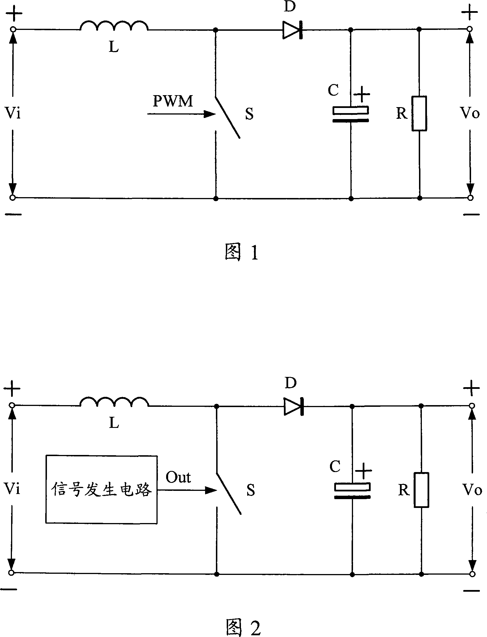
[0025] Since the harmonic components contained in the externally provided PWM pulse signal will eventually be coupled into the circuit of the whole machine, which will bring great noise interference to the whole machine, the basic idea of ​​the present invention is to integrate a low-cost signal generating circuit to replace Provide external PWM pulse, only need to provide input voltage in practical application, the output will get the ideal boost value, reduce the cost of circuit development, greatly facilitate the design and use needs.

[0026] Figure 2 shows a schematic diagram of the principle of the present invention. Compared with the existing boost circuit in th...


PUM


Abstract

The invention discloses a voltage booster circuit, the development cost and the maintenance cost of which are lower. The voltage booster circuit comprises a switch, and further has a signal generating circuit, wherein the signal generating circuit outputs a pulse signal to control the opening and the closing of the switch. The invention is widely applied to consumption electronic products.

Description

technical field [0001] The invention relates to a voltage boosting circuit, in particular to a voltage boosting circuit which internally provides a control signal. Background technique [0002] In the design of many consumer electronics products, power supply design is often the difficulty of design, and efficient, stable and reliable power supply scheme design has always been the pursuit goal of technicians and researchers. With the increasingly fierce competition of consumer electronics products, low-cost and high-performance power supply designs are increasingly favored by manufacturers. [0003] As the power supply of consumer electronic products, the booster circuit currently has two main solutions. The first is to use a dedicated booster circuit chip, and the second is to use resistance capacitance and transistors to build a dedicated booster circuit according to specific applications. The performance of the boost circuit provided by the dedicated chip is good, but th...

Claims


Application Information

Patent Timeline
Patent Type & Authority Applications(China)
IPC IPC(8): H02M3/07
Inventor 张辉王西强孟斐
Owner 新奇点智能科技集团有限公司
Why Eureka
Try Eureka