This helps you quickly interpret patents by identifying the three key elements:
Problems solved by technology
Method used
Benefits of technology
Problems solved by technology
As a result, in metal diaphragm valves that only switch between fully closed and fully open, the flow rate increases. In addition, in metal diaphragm valves for flow / pressure control, the relationship between valve opening and flow rate changes over time. Problems with High Accuracy Flow / Pressure Control
Method used
Image
Click on the blue label to locate the original text in one second.
Reading with bidirectional positioning of images and text.
Examples
specific example 1
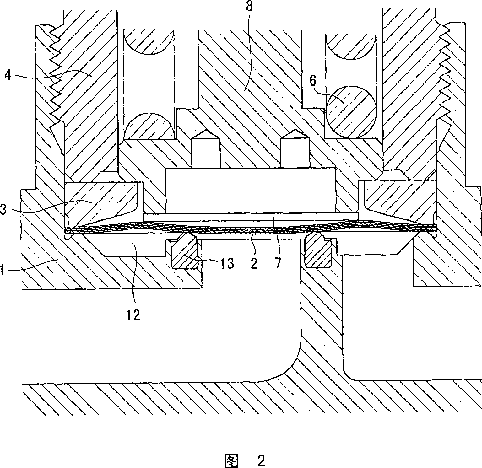
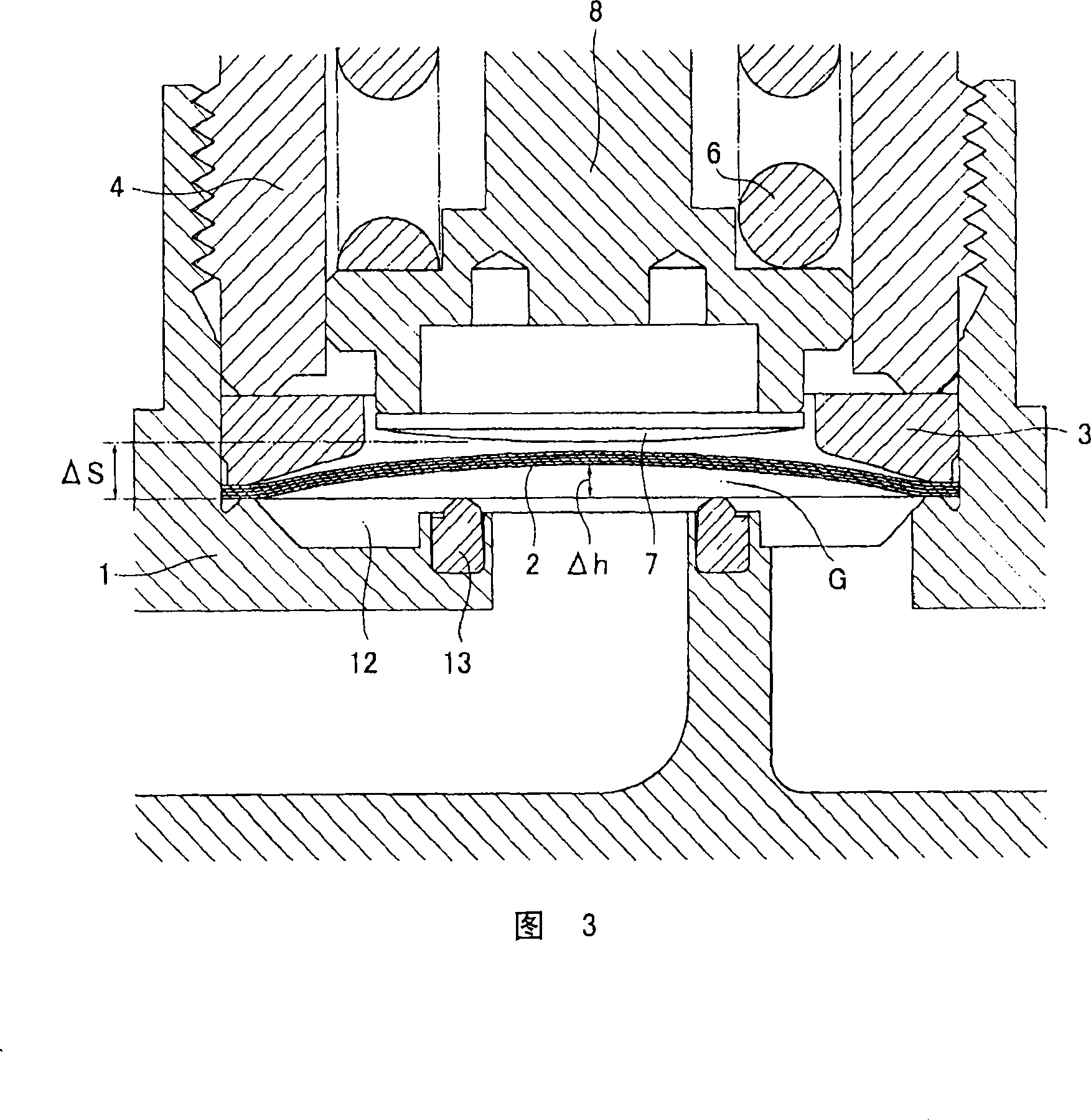
[0109] Referring to Fig. 2, Fig. 2 is a partially enlarged view showing the closed state of the valve using the metal diaphragm 2 of the above-mentioned embodiment 1, and Fig. 3 is a diagram showing the use of the metal diaphragm 2 of the embodiment 1 when the valve stroke ΔS is 1.5mm. Partial enlarged view of the valve opening state.
[0110] In Fig. 2 and Fig. 3, the valve stroke ΔS is selected as 1.5mm, and the valve stroke ΔS is larger than the maximum bulge height Δh=1.2mm of the metal diaphragm 2, so the metal diaphragm 2 is completely restored to its original state.
specific example 2
[0112] On the other hand, Fig. 4 and Fig. 5 show the closed state ( Fig. 4 ) and the valve open state when the valve stroke ΔS is set to 0.7 mm in the valve of Fig. 1 using the metal diaphragm 2 of the first embodiment described above. (FIG. 5) A partially enlarged view of the state. When the valve is closed, the metal diaphragm 2 does not return to the complete original state as shown in FIG. 3, but becomes a somewhat deformed state.
[0113] That is, when the valve stroke ΔS is reduced, the amount of deformation of the metal diaphragm 2 becomes smaller, and the deformation stress acting on the metal diaphragm 2 becomes relatively smaller.
[0114] In the case of the valve stroke ΔS=1.5mm and ΔS=0.7mm, there is a large difference in the form of the metal diaphragm 2 as described above, but the distance between the valve seat 3 and the inner surface of the metal diaphragm 2 can be judged. Gap G did not change much.
specific example 3
[0116] 6 and 7 show that the metal diaphragm valve of FIG. 1 using the metal diaphragm 2 of the above-mentioned embodiment 1 is used to measure the flow rate using the Cv value measurement test device of the above-mentioned FIG. 8, and the Cv value is obtained by using the above-mentioned (2) formula In addition, Table 1 is a list of the above-mentioned lift and flow and Cv values.
[0117] Among them, the test was carried out under the conditions of an operating air pressure of 0.55 MPa and a protrusion height of the valve seat of 0.128 mm (height after baking at 80°C).
[0118] 【Table 1】
[0119] Lift(mm)
[0120] It can be seen from FIG. 6 and FIG. 7 that the valve stroke ΔS=about 0.65-0.8, and the Cv value=0.55-0.6 required by the valve can be realized. That is, it is preferable to realize a Cv value of 0.6 by setting the valve stroke ΔS=0.7 mm, and it can be seen that the metal diaphragm 2 does not need to be deformed to the maximum until the valve stroke reach...
PUM
Abstract
In the direct contact typemetaldiaphragm valve, the durability of the valve, that is, the number of continuous opening and closing operations of the valve that can be guaranteed, is greatly increased while maintaining an appropriate flow coefficient Cv, and the deformation of the valve seat over time is suppressed, so that the above-mentioned Cv The temporal fluctuation of the value becomes smaller. In the direct contact typemetaldiaphragm valve, the metal diaphragm is made of a laminated body of a plurality of metal steel thin plates and nickel-cobaltalloy thin plates and is formed into a circular inverted disk shape with the central part raised upwards, and the metal thin film The distance of 55-70% of the maximum bulge height Δh is limited to the maximum valve stroke ΔS of the valve.
Description
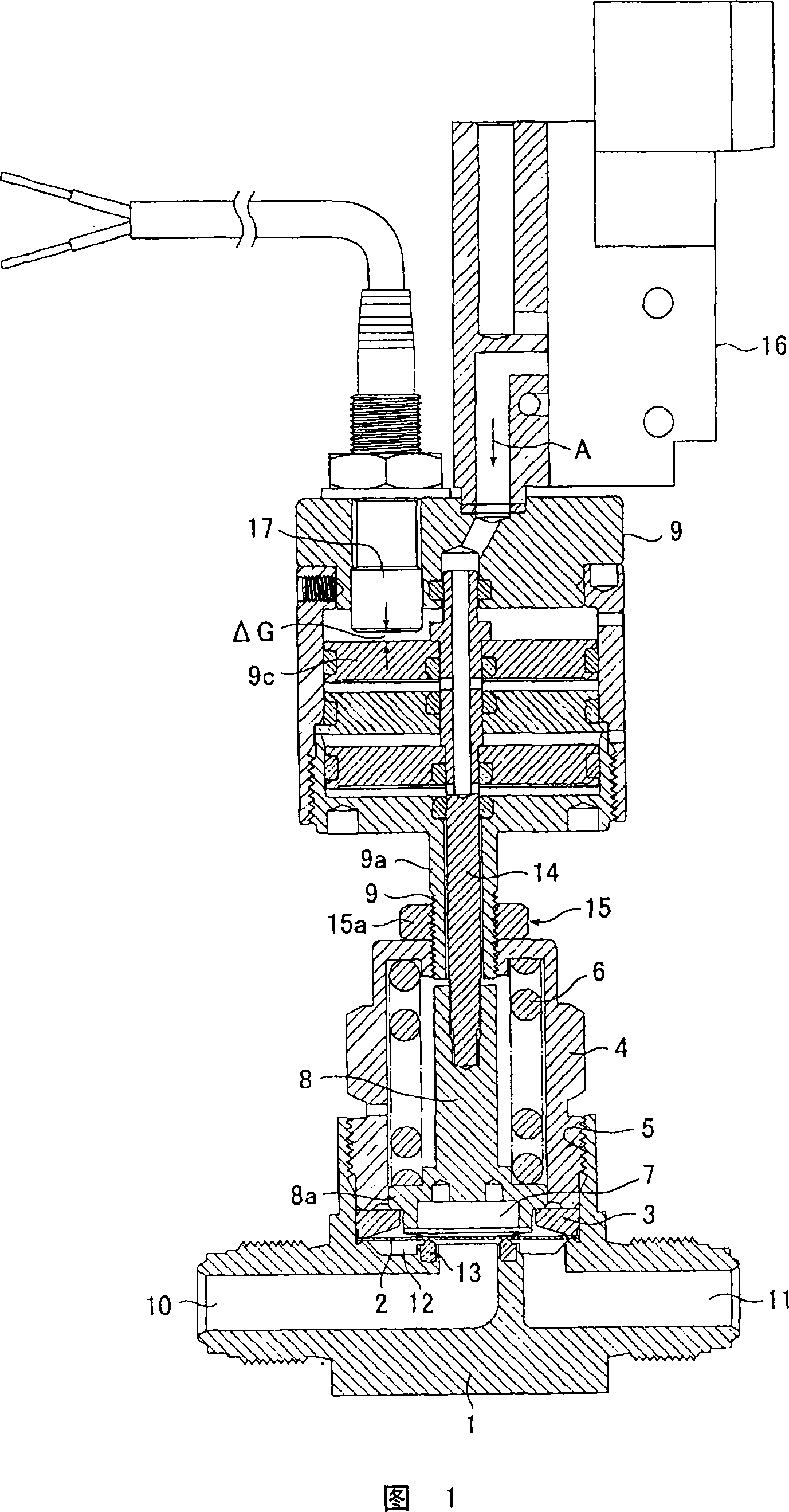
technical field [0001] The present invention mainly relates to a direct-contact metal diaphragm valve used in a gas supplysystem of a semiconductor manufacturing facility, etc., and relates to a valve capable of greatly increasing the number of times the valve is opened and closed, and by stably maintaining the flow coefficient of the valve to reduce fluctuations in flow rate characteristics. High-durability direct contact metal diaphragm valves that are less expensive. Background technique [0002] Direct contact metal diaphragm valves (hereinafter referred to as metal diaphragm valves) generally have the structure shown in Figure 10, which not only has good responsiveness and fluid displacement, but also has the characteristics of being close to particles, so it is used in semiconductor manufacturing equipment and chemical industry. It is widely used in fields such as industrial equipment and food industry equipment. [0003] That is, in FIG. 10, 21 is a main body, 22 is...
Claims
Application Information
Patent Timeline
Application Date:The date an application was filed.
Publication Date:The date a patent or application was officially published.
First Publication Date:The earliest publication date of a patent with the same application number.
Issue Date:Publication date of the patent grant document.
PCT Entry Date:The Entry date of PCT National Phase.
Estimated Expiry Date:The statutory expiry date of a patent right according to the Patent Law, and it is the longest term of protection that the patent right can achieve without the termination of the patent right due to other reasons(Term extension factor has been taken into account ).
Invalid Date:Actual expiry date is based on effective date or publication date of legal transaction data of invalid patent.

