Hybrid vehicle with engine power cylinder deactivation

A hybrid vehicle and engine technology, applied in hybrid vehicles, engine-driven traction, motor vehicles, etc., can solve the problem that energy cannot be captured regeneratively, and achieve the effect of improving regenerative performance and fuel combustion efficiency

Inactive Publication Date: 2008-08-06
FORD GLOBAL TECH LLC
View PDF1 Cites 10 Cited by
  • Summary
  • Abstract
  • Description
  • Claims
  • Application Information

AI Technical Summary

Problems solved by technology

This is an undesirable situation from the point of view of maximizing regenerativ...

Method used


Image

  • Hybrid vehicle with engine power cylinder deactivation
  • Hybrid vehicle with engine power cylinder deactivation
  • Hybrid vehicle with engine power cylinder deactivation

Examples


Embodiment Construction

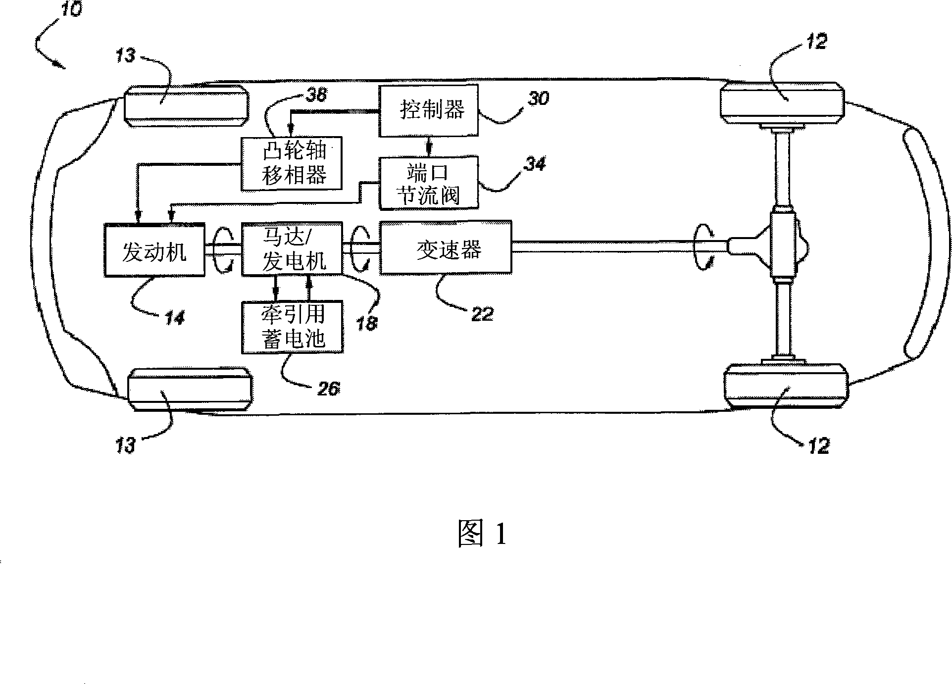
[0019] As shown in FIG. 1 , a vehicle 10 has a plurality of road wheels 12 that are steered by a powertrain system including an engine 14 , a motor / generator 18 and a transmission 22 . Walking wheel 13 is unpowered. Engine 14 and motor / generator 18 are rotationally coupled together such that engine 14 generally rotates in unison with motor / generator 18 . This configuration can be seen in so-called "soft" hybrid vehicles, which have the advantage of lower initial cost, although this comes at the expense of reduced regenerative performance. As previously stated, the present invention seeks to enhance regenerative performance, and such regenerative performance may be used on vehicle 10 .

[0020] As the name implies, the function of the motor / generator 18 is not only to obtain power from the traction battery 26 as a traction motor and drive the road wheels 12 through the transmission 22; the motor / generator 18 can also be used as a generator during regenerative braking, so that ...


PUM


Abstract

A hybrid vehicle includes a reciprocating internal combustion engine having intake and exhaust poppet valves which are controlled so as to minimize the amount of power required to motor the engine during regenerative braking, so as to maximize energy stored within an energy storage device recharged by a rotating reversible machine operatively connected with the engine, the vehicle's road wheels, and the energy storage device.

Description

technical field [0001] The present invention relates to a hybrid vehicle having an internal combustion engine and a rotary reversible mechanism coupled to the internal combustion engine for selectively powering the road wheels and regenerative braking performance enhanced by manipulating engine cylinder valves to enable The drive horsepower of the engine is minimized during regenerative braking. Background technique [0002] There are various types of hybrid vehicles. A common type of so-called "soft" hybrid includes an internal combustion engine driving the road wheels through a transmission. In soft mixing, a rotating reversible machine, such as an electric motor / generator or a hydraulic pump / motor, is coupled to the engine so that it rotates with the engine crankshaft. So whenever the engine spins, the reversible mechanism spins with it. Since the engine rotates synchronously with the reversible machinery, regenerative braking of this vehicle not only causes the vehicl...

Claims


Application Information

Patent Timeline
IPC IPC(8): B60W20/00F02D13/02B60L7/24B60L50/16B60W30/18
CPCY02T10/6286F01L2001/0537F02D13/04B60W2550/12B60K6/48F01L1/34F02D17/02F02D13/06B60W30/18127B60W20/00B60W10/06F02D13/0203F01L2013/001B60W10/08F01L2800/00Y02T10/6221F01L13/0005B60W2555/20Y02T10/62F01L13/06F02D13/08B60W2510/06B60W10/04B60W2510/24B60W20/15B60W2050/001
Inventor 托马斯·利昂
Owner FORD GLOBAL TECH LLC
Why Eureka
Try Eureka