Straight-line rolling slipper block and method of manufacture

A manufacturing method and slider technology, applied in the direction of linear motion bearings, bearings, shafts and bearings, etc., can solve the problem that the actual accuracy and roughness of wire cutting can not meet the actual use requirements, affect the service life and stability, and friction Increased resistance and other issues, to achieve the effect of small friction coefficient, stable and precise upper and lower contact, and low heat generation

Inactive Publication Date: 2008-08-06
宁波恒力汽配轴承有限公司
View PDF1 Cites 22 Cited by
  • Summary
  • Abstract
  • Description
  • Claims
  • Application Information

AI Technical Summary

Problems solved by technology

Although this method does not require a rolling body retaining device, the actual precision and roughness of the wire cutting cannot meet the actual use requirements. Therefore, the surface roughness of the raceway is increased in a short time during acceleration or load operation, so that the balls are in the high and low position. Rolling in the uneven raceway will cause a sharp increase in friction resistance. If it runs at high speed, it will easily generate friction heat, which will cause the sliding block to heat up quickly. Long-term high-temperature and high-speed operation will seriously affect the service life.
Therefore, this production method still has not solved the problem of affecting service life and stability during long-term high-temperature and high-speed operation.

Method used


Image

  • Straight-line rolling slipper block and method of manufacture

Examples


Embodiment Construction

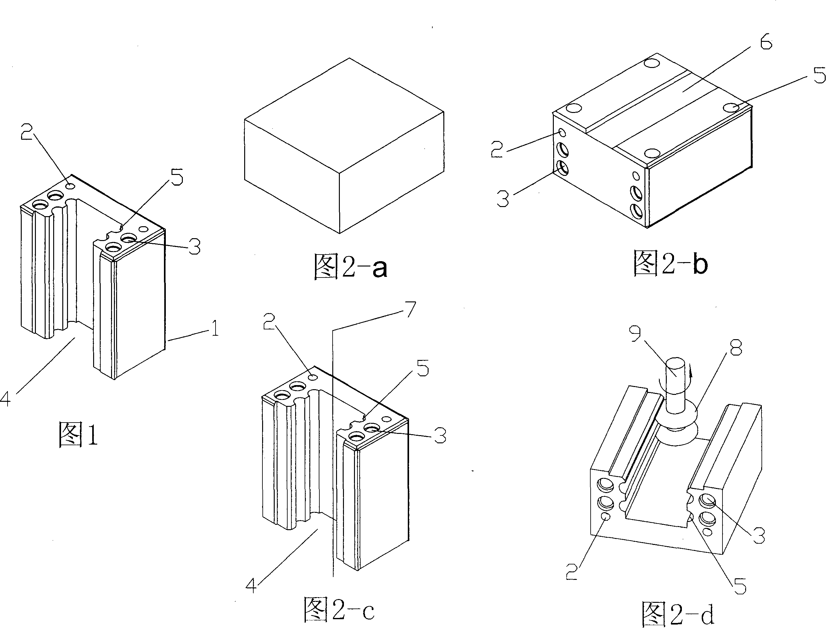
[0018] Metal slider body manufacturing method:

[0019] Metal slider body processing flow chart 2 shows that the slider body is made of high-quality bearing steel from Shanghai No. The best material for the body.

[0020] First, the bearing steel round bar is blanked on the cutting machine according to the tolerance requirements of the hot forging specification, and the dropped broken material is placed in the furnace to heat it to about 1000°C before hot forging, and each section of material is kept warm until the material is red. Forging. Forging and pressing use special molds to forge and press square green body blocks on 150T to 200T forging presses. The special mold material for forging is 5crMnMo, because of its good heat resistance and vibration resistance, long service life and durability.

[0021] Spheroidizing and annealing the forging and pressing blank. After putting the square blank in the annealing furnace, raise the furnace temperature to HRC750°C, keep it wa...


PUM


Abstract

The invention relates to a linear rolling slider, which comprises a rolling steel ball which is arranged in the slider, an upper raceway groove and a lower raceway groove which are parallel are arranged on the inner walls of the two sides of an inner concave slider, and a raceway cavity which is reversely connected with the upper raceway groove and the lower raceway groove is horizontally arranged on the inner walls of the two sides of the inner concave slider. The method for preparation comprises that a round steel bar is thermally forged into a square green body, the square green body is milled and processed into cut angle end surfaces which are mutually vertical, and relative surfaces are hexahedron which are mutually parallel. The hexahedron is flatly ground and processed to achieve the required precision of parallelism and reference location, the hexahedron is cut and processed into a concave slider body by a wire electrical discharge, and an upper semi-circle raceway groove and a lower semi-circle raceway groove which are parallel and are arranged on the two sides of the inner concave slider are ground in high speed. A steel ball in the raceway groove not only operates in high speed not to block, but also is not bore in long time operation and not produces frictional heating. The friction coefficient is capable of being reduced to fiftieth of the original friction coefficient, the instantaneous speed is increased for 10 times, the linear rolling slider uses a double-row raceway groove, thereby being capable of greatly increasing carrier loads, achieving steady operation, and prolonging the service life.

Description

technical field [0001] The invention relates to a linear rolling slider and a manufacturing method thereof. Background technique [0002] The traditional linear slider, such as the slider seat matched with the linear square guide rail, mostly uses surface contact sliding. The sliding friction resistance and friction coefficient between the guide rail surface and the slider surface are very large. If it runs at high speed, it is easy to generate friction heat. The moving slider heats up quickly, and long-term high-temperature and high-speed operation affects the service life. When adding lubricating oil, due to the countercurrent effect of the oil film and insufficient lubrication on each sliding surface, the contact surface of the running track will be severely worn, which will affect the working accuracy and the stability of the movement. CN100348353C proposes a rolling slider manufacturing method of a linear ball guide rail. The cutting of the center position of the rolli...

Claims


Application Information

Patent Timeline
Patent Type & Authority Applications(China)
IPC IPC(8): F16C29/06
Inventor 郑世良梅雪成
Owner 宁波恒力汽配轴承有限公司
Why Eureka
Try Eureka