Visual light navigation sensor

A sensor and visible light technology, applied in the field of navigation sensors, can solve the problems of difficulty in star point extraction, difficulty in target extraction, errors, etc., and achieve the effects of enhancing the detection sensitivity of the system, simplifying the difficulty of target extraction, and improving the data update rate.

Active Publication Date: 2008-08-06
BEIJING INST OF CONTROL ENG
View PDF3 Cites 24 Cited by
  • Summary
  • Abstract
  • Description
  • Claims
  • Application Information

AI Technical Summary

Problems solved by technology

[0004] U.S. Patent No.: US5837894, title: Wide Field of View Sensor with diffractiveOptical Corrector, this patent discloses a three-axis earth attitude sensor using the ultraviolet spectrum, the difference from the present invention lies in the target difference, and the present invention is not used for earth satellites It is mainly used for stars with thin atmospheres outside the earth. In addition, its disadvantage is that it does not divide the stars, the earth's field of view channel and the imaging area, making it very difficult to process and identify the earth and stars in information processing; in addition, it uses a unified The ultraviolet spectrum makes the energy of the stars and the earth weak, and an image intensifier must be added to amplify the signal in order to image normally
[0005] U.S. Patent No.: US5319969, name: Method for determining 3-axis spacecraftattitude, this patent introduces a three-axis attitude determination method using ultraviolet spectrum attitude sensor, including image preprocessing, bright edge extraction and attitude calculation, it requires The ephemeris information calculates the earth imaging model in orbit and obtains the attitude angle by comparing the measurement information, which is cumbersome
[0006] U.S. Patent No.: US5189295, name: Three axis earth / star sensor, this patent introduces a three-axis attitude sensor using the visible spectrum segment, its shortcoming is that it is sensitive to the earth using the visible spectrum segment and is easily affected by the atmosphere to cause errors , in addition, the segmentation of the imaging area is not performed, which makes subsequent star point extraction and earth edge extraction very difficult
[0007] Article: "Combined Earth / Star Sensor for attitude and orbit determination of geostationary satellites" PHD Paper of Christopher T.F.kuhl, University of Stuttgart Germany 2005, introduced Germany's visible light earth / star sensor for earth satellites, the shortcoming is that it does not have a field of view Channel division, the stars and the earth are imaged in the same area, it is not easy to extract the target

Method used


Image

  • Visual light navigation sensor
  • Visual light navigation sensor
  • Visual light navigation sensor

Examples


Embodiment Construction

[0037] Below in conjunction with accompanying drawing and specific embodiment the present invention is described in further detail:

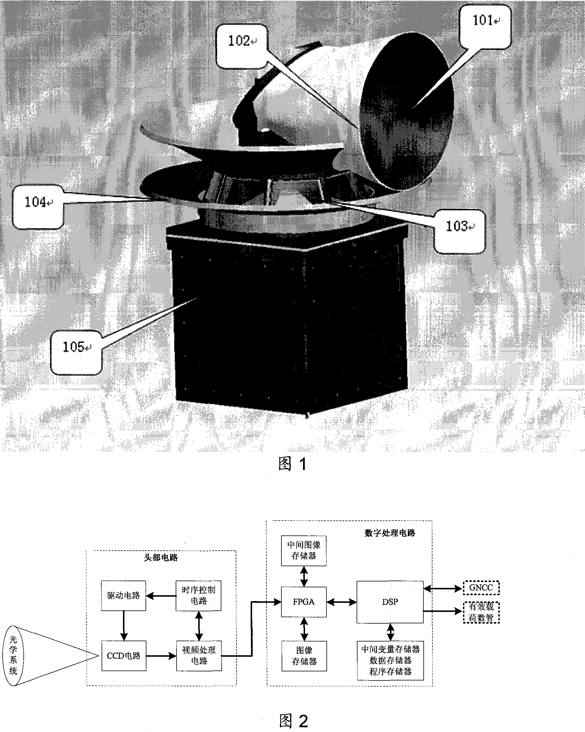
[0038] Fig. 1 is the overall structure diagram of the visible light navigation sensor of the present invention. The visible light navigation sensor includes an optical system, a circuit system, an image and an attitude calculation unit. The image processing and attitude calculation algorithms are solidified in the PROM chip of the circuit system. The optical system and the circuit system are fixedly connected to form an integrated whole machine system. Emulator and a power supply. The circuit system includes a head circuit and a digital processing circuit; the head circuit converts the optical signal into an electrical signal, and converts it into a digital image signal through video processing and AD conversion; the digital processing circuit completes the information processing of the digital image signal and outputs it to the navigation comp...


PUM


Abstract

The invention discloses a visible light navigation sensor, which employs visible light spectrum bands with different widths and a dual-channel optical system to image different objects to independent areas of a target surface of a same photodetector. The optical system is divided into two independent viewing field channels which respectively image quasars and stars. The photodetector convert images of the quasars and the stars into simulating signal to output. An electrical system processes the stimulating signal and converts to obtain digital images. At last, an image and attitude computing element respectively processes the quasar image information and the stars image information to compute and obtain a quasar center vector, an orbit height and an inertial attitude needed by satellite navigation. The visible light navigation sensor employs the technique of the visible light spectrum bands with different widths, sub-viewing-fields and sub-image-areas to resolve the problem that the photodetector simultaneously images the quasar and the stars on the same target surface. In addition, the visible light navigation sensor has a normal imaging mode and a binning imaging mode.

Description

technical field [0001] The invention relates to a visible light navigation sensor, which belongs to the field of navigation sensors in attitude track control systems on spacecraft. The invention is suitable for relative attitude measurement and navigation of stars without atmosphere or with thin atmosphere in deep space probes. Background technique [0002] Deep space exploration is a hot spot in the development of aerospace technology. The main goal is to launch spacecraft for scientific exploration of extraterrestrial bodies, such as lunar exploration, Mars, asteroid exploration, etc. large spacecraft navigation problems. The rapid progress of imaging detection devices and processor technology and the successful in-orbit flight of imaging star sensors, imaging earth and moon sensors have made the integrated near-stellar / star navigation sensor a development direction. Giving the three-axis satellite attitude of a relatively near star can also give the orbital position, wh...

Claims


Application Information

Patent Timeline
IPC IPC(8): G01C21/24G01C21/02G01C21/20B64G1/36
Inventor 王立卢欣尉志军龚德铸刘鲁
Owner BEIJING INST OF CONTROL ENG
Why Eureka
Try Eureka