Heliostat device

A technology of heliostats and plane mirrors, applied in the field of solar energy applications, can solve the problems of difficult mass modular production, large quantity, and enlarged area, and achieve the effects of reducing the difficulty of production and installation and debugging, reducing costs, and reducing precision requirements

Inactive Publication Date: 2008-08-06
苏建国
View PDF0 Cites 48 Cited by
  • Summary
  • Abstract
  • Description
  • Claims
  • Application Information

AI Technical Summary

Problems solved by technology

[0006] In a tower-type solar thermal power station, since each heliostat has different orientations and distances relative to the central tower, the tracking of each heliostat must be individually and differently controlled in two dimensions, which greatly increases The complexity of the control system and the difficulty of installation and debugging, especially optical adjustment
The extremely complex control system is expensive and the quantity is huge. In order to reduce the use of control system equipment, people make the area of ​​a single heliostat larger, generally 20M 2 above
If the overall performance of large-area heliostats is to meet the above-mentioned basic requirements, not only is the cost high (the cost increases exponentially as the area increases), but it is also difficult to produce on a large scale
[0007] Over the years, tower-type solar thermal power generation has been facing many difficulties and cannot be industrialized. The biggest obstacle is the high cost of heliostat devices, the difficulty of mass modular production, and the difficulty of installation, commissioning and maintenance.

Method used


Image

  • Heliostat device
  • Heliostat device
  • Heliostat device

Examples


Embodiment 1

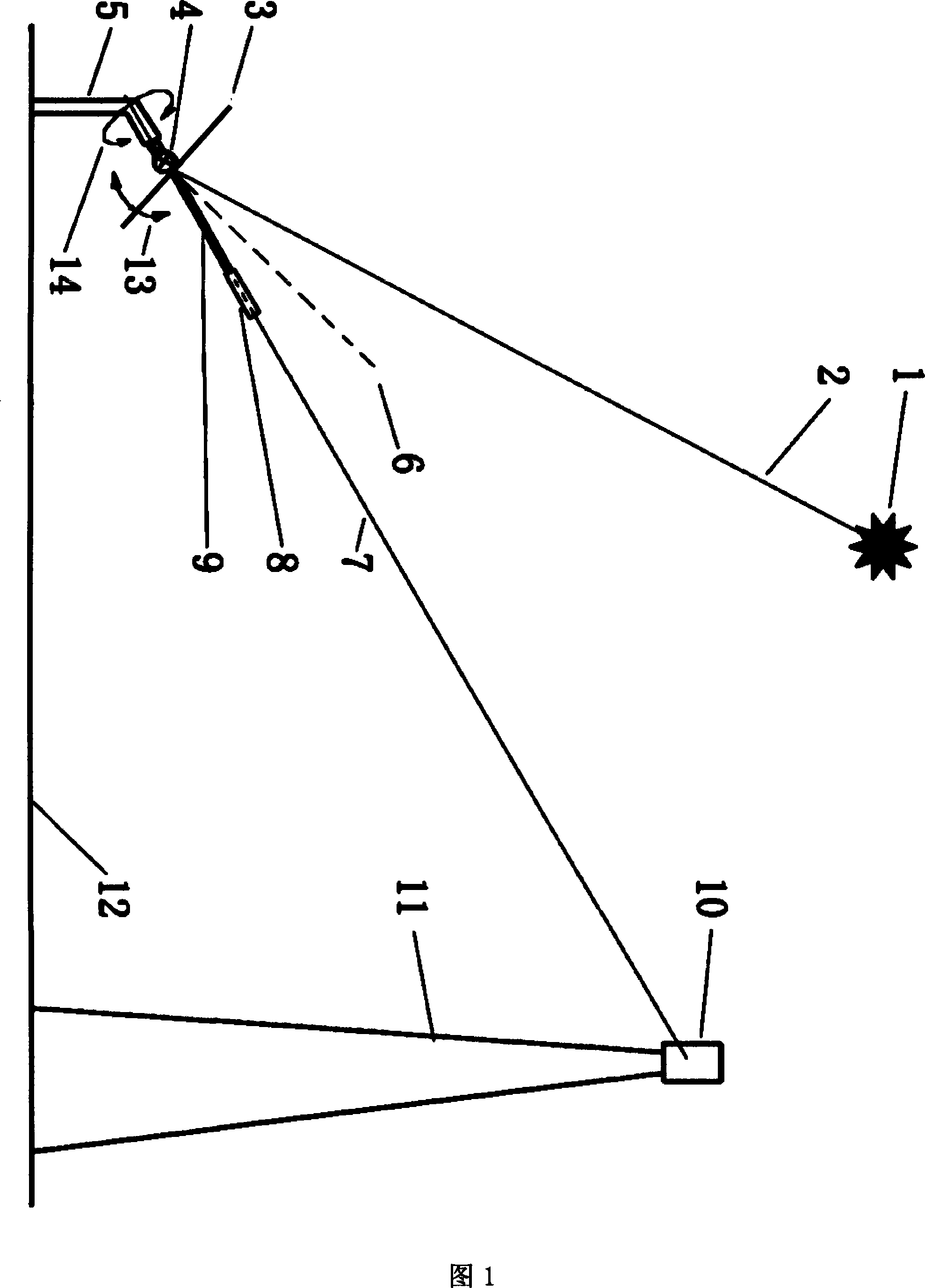
[0024] This embodiment adopts the spin plus elevation angle tracking method, as shown in FIG. 1 . It is composed of a mirror 3, an elevation angle adjustment mechanism 4, a bracket 5, a positioning sensor group 8, and the like. The mirror surface 3 is a flat mirror with sufficient strength. 11 is the receiving tower, 12 is the ground, 13 is the elevation adjustment direction of the mirror 3, and 14 is the spin adjustment direction of the mirror 3. The reflected light 7 irradiated to the bull's-eye of the heat collector 10 is the reflected light 2 emitted by the sun 1 and irradiated on the mirror 3 . 6 is the vertical line of the mirror surface 3. The centerline of the positioning sensor group 8 is parallel to the centerline of the pointing tube 9 . As long as the reflected light 7 can pass through the positioning guide tube and reach the center of the four-quadrant photosensitive element of the positioning sensor group 8, it can be ensured that the reflected light spot of t...

Embodiment 2

[0031] The schematic diagram of the heliostat device in this embodiment is shown in Figure 6, which adopts the azimuth plus elevation angle tracking method. It consists of a mirror 3, an elevation angle adjustment mechanism 4, a bracket 5, a positioning sensor group 8, a positioning sensor group bracket 9, and the like. 11 is the receiving tower, 12 is the ground, 13 is the elevation adjustment direction of the mirror 3, and 14 is the azimuth adjustment direction of the mirror 3. The reflected light 7 irradiated to the bull's-eye of the heat collector 10 is the reflected light 2 emitted by the sun 1 and irradiated on the mirror 3 . 6 is the vertical line of the mirror surface 3. The center line of the positioning sensor group 8 coincides with the line connecting the center point of the mirror surface 3 and the bull's-eye of the heat collector 10 . As long as the reflected light 7 can pass through the positioning guide tube and reach the positioning sensor group 8 , it can be...


PUM


Abstract

The invention relates to a plane mirror being capable of projecting sunlight directionally which is the usually-called Tingri mirror and belongs to the solar energy application technical field. In the device, positioning plus elevation tracking or auto-rotating plus elevation tracking is adopted; the device comprises a plane mirror, a frame with a dimension small enough to be formed at one time, an adjusting device, a positioning and guiding pipe arranged a center tower and the Tingri mirror, a positioning sensor and a control system which carries out control and error judgment according to signals produced by reflection light reaching a mirror surface of a four-quadrant photosensitive element through the positioning and guiding pipe. If the invention is adopted, as long as sunlight, no matter where the sun move, the reflection light of the Tingri mirror can always project into a collector. Due to the adoption of the positioning and guiding pipe, the positioning sensor and DCS (distributed control system), a mirror with a small area can be used, reducing the difficulty in production, installation and commissioning and thus reducing the cost significantly.

Description

technical field [0001] The invention relates to a flat mirror device for directional projection of sunlight, that is, a device commonly called a heliostat, and belongs to the technical field of solar energy applications. Background technique [0002] Solar energy as a renewable energy source has the following advantages: it does not have harmful gases and waste residues produced by fossil fuels such as general coal and petroleum, so it does not pollute the environment and is called "clean energy"; solar energy can be obtained everywhere, and it is easy to use, safe, Inexpensive and reproducible. Among the various ways of using solar power, the tower solar thermal power generation has its obvious advantages: high concentration multiple, easy to reach a higher working temperature; the more heliostats in the array, the greater the concentration ratio , the higher the heat collection temperature of the receiver; the energy concentration process is completed by reflecting light ...

Claims


Application Information

Patent Timeline
Patent Type & Authority Applications(China)
IPC IPC(8): G02B7/182G02B7/198G05D1/08G05D3/00F24J2/38F24S50/20
CPCF24J2/38Y02E10/47F24J2/54F24S50/20F24S30/40
Inventor 苏建国
Owner 苏建国
Why Eureka
Try Eureka