Flying plate driving type laser micro-welding method and device

A welding method and driving technology, applied in laser welding equipment, welding equipment, non-electric welding equipment and other directions, can solve the problems of human body harm, affect the quality of the workpiece, easy to damage the workpiece, etc., and achieve the effect of increasing flexibility

Inactive Publication Date: 2008-08-13
JIANGSU UNIV
View PDF2 Cites 35 Cited by
  • Summary
  • Abstract
  • Description
  • Claims
  • Application Information

AI Technical Summary

Problems solved by technology

[0005] 1. The explosive energy is difficult to control precisely, making the welding process parameters unstable
[0006] 2. Explosives directly act on the surface of the workpiece, affecting the quality of the workpiece
[0

Method used


Image

  • Flying plate driving type laser micro-welding method and device

Examples


Embodiment Construction

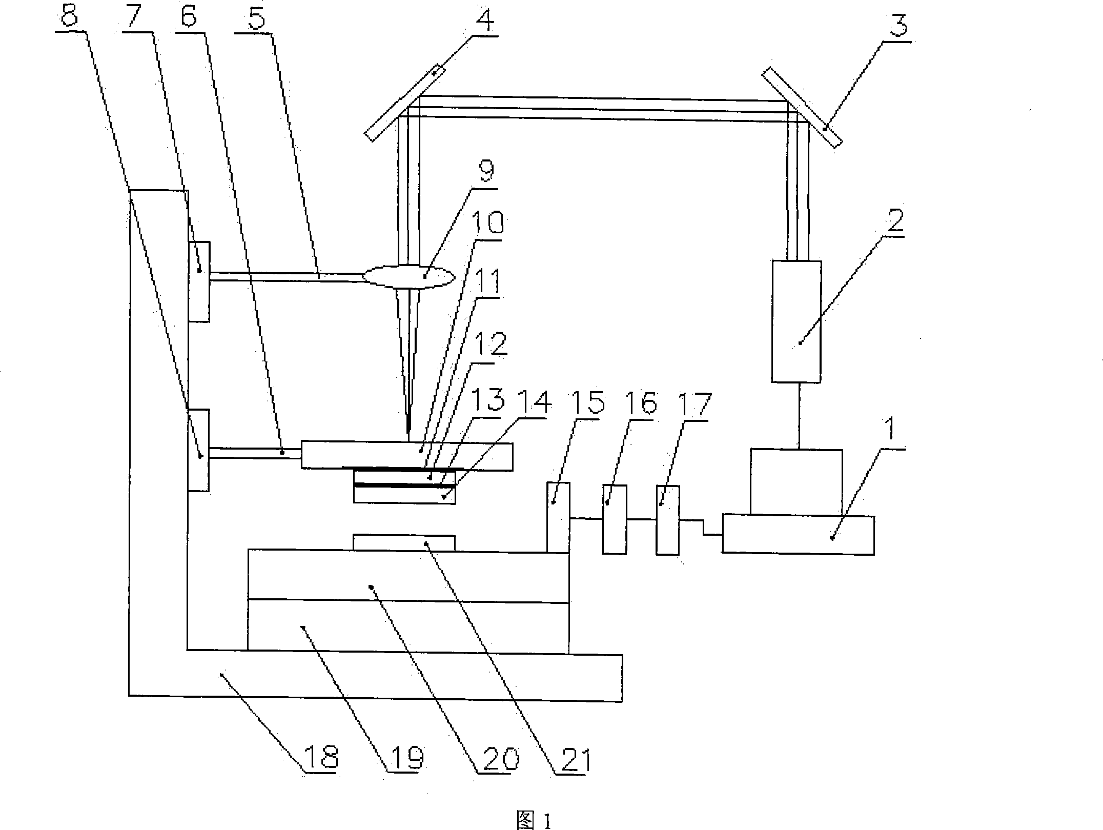
[0023] The flyer-driven laser micro-welding device proposed by the present invention is shown in Fig. 1, and the whole welding device is composed of 21 parts. The specific implementation process is as follows, taking an aluminum foil workpiece with a diameter of 1 mm and a thickness of 10 μm and a diameter of 1 mm and a thickness of 30 μm

[0024] μm aluminum foil substrate welding as an example.

[0025] First prepare flyer 12, workpiece 14 and substrate 21, and use a femtosecond laser to cut the aluminum foil into a workpiece 13 with a diameter of 1 mm and a thickness of 10 μm, the diameter of the flyer 12 is 1 mm, the thickness is 10 μm, and the substrate 20 is 1 mm in diameter and 30 μm in thickness. After the annealing treatment, clean the surface with anhydrous alcohol, and after drying, press it with two flat K9 glass for future use, the purpose is to ensure the flatness.

[0026] Then drop a drop of silicone oil in the middle of the constraint layer 10 to form the fir...


PUM


Abstract

The invention relates to welding field, especially relates to a flying slice driving laser microwelding method and device, adapted to quick welding between homogeneous or heterogeneous metallic materials. The invented device is composed of a laser, a reflection mirror, a focusing lens, a focusing lens supporting frame, a focusing lens moving platform, a confinement layer, a confinement layer supporting frame, a confinement layer moving platform, a worktable, a three-dimensional moving platform, a L-shaped base, a CCD cam, a D/A converter, an image gathering card, and a computer. The single pulse laser controlled by the computer accurately acts on the front surface of the flying slice to generate explosion plasma which drives the workpiece adhering tightly to the back of the flying slice to moving with a high speed while driving the flying slice moving with a high speed, the flying slice collides with the base after flying for a distance, and high temperature and high pressure are generated on the colliding boundary to implement welding between the workpiece and the base. The invented method and device realize low cost and high efficiency of microwelding, are provided with simple technique and good compatibility, and are suitable for automated production.

Description

technical field [0001] The invention relates to the field of welding, in particular to a flyer-driven laser micro-welding method and device, which is suitable for rapid welding between the same or different metal materials, especially suitable for welding micro-metal devices, and can ensure high micro-welding Quality and high efficiency. Background of the invention [0002] Micro-devices are more and more widely used in various fields such as aerospace, medical and health, telecommunication electronics, precision instruments and national defense. Traditional micro-forming technology is limited by material properties and micro-scale factors, which brings great challenges to the processing of micro-devices. It is difficult to rely solely on the plastic forming technology of materials to meet the needs of industrial production. Welding technology plays an important role in the manufacturing industry because it can quickly and effectively realize the connection of materials of ...

Claims


Application Information

Patent Timeline
IPC IPC(8): B23K20/12B23K20/14B23K26/04B23K26/08
Inventor 王霄杨昆刘会霞张惠中王匀周明蔡兰
Owner JIANGSU UNIV
Why Eureka
Try Eureka