Solar battery chip protection structure

A solar cell and protective structure technology, applied in the field of solar energy, can solve the problems of reducing the fill factor, affecting the efficiency and life of the battery, and increasing the cost, so as to achieve the effects of increasing the fill factor, improving the effective utilization rate, and prolonging the service life

Inactive Publication Date: 2008-08-13
GENIUS ELECTRONICS OPTICAL XIAMEN
View PDF0 Cites 4 Cited by
  • Summary
  • Abstract
  • Description
  • Claims
  • Application Information

AI Technical Summary

Problems solved by technology

[0003] With the further widespread application of solar energy, high light intensity in the field of solar energy can improve the fill factor of solar cells and effectively reduce costs, but if the light is too strong, the temperature rise will melt or break the PCB board outside the chip, so scientific and reasonable treatment "Concentration remaining outside the chip" is very important. This point is one of the key issues in the application of the entire battery, which directly determines the life of the solar concentrati

Method used


Image

  • Solar battery chip protection structure
  • Solar battery chip protection structure
  • Solar battery chip protection structure

Examples


Embodiment Construction

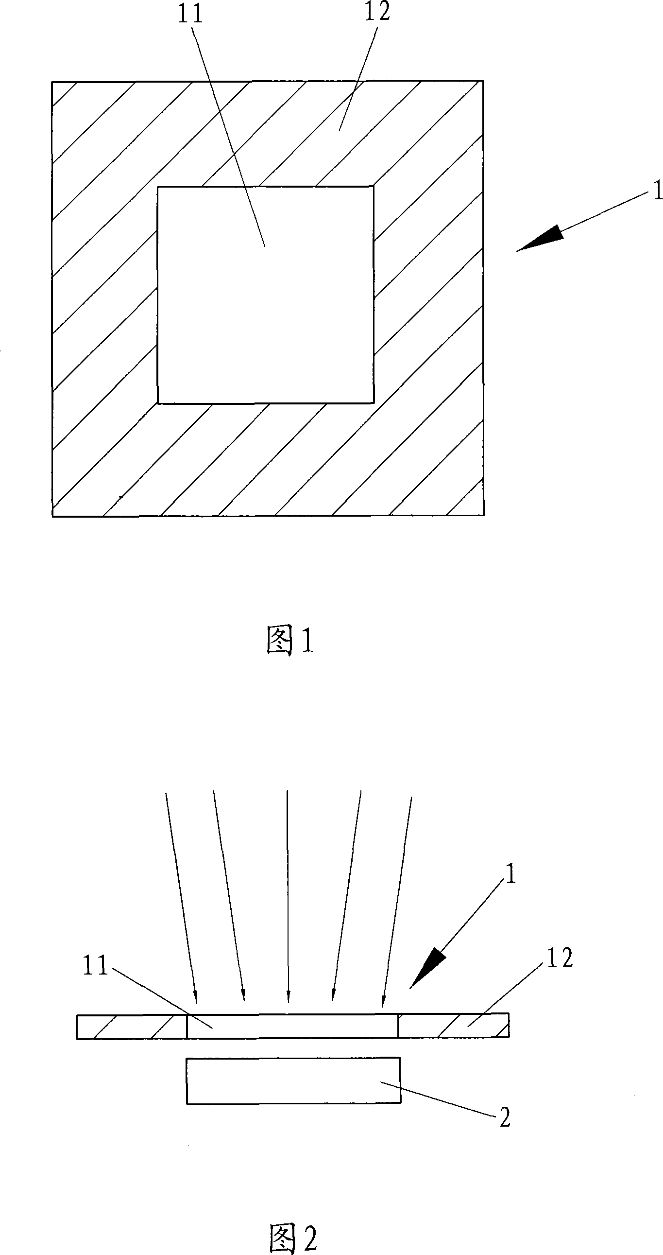
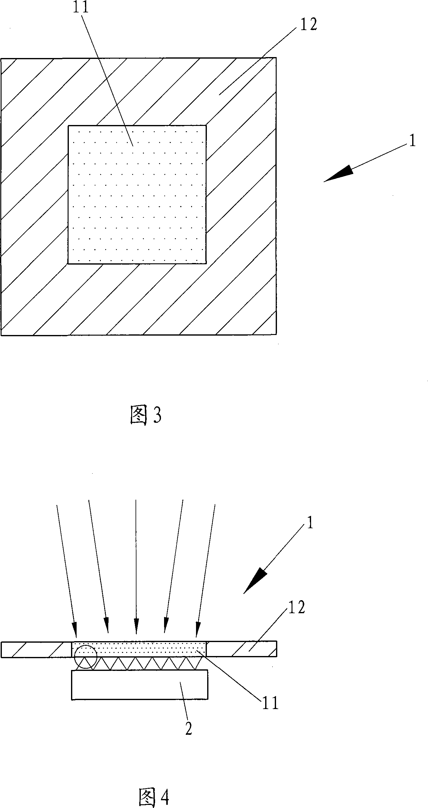
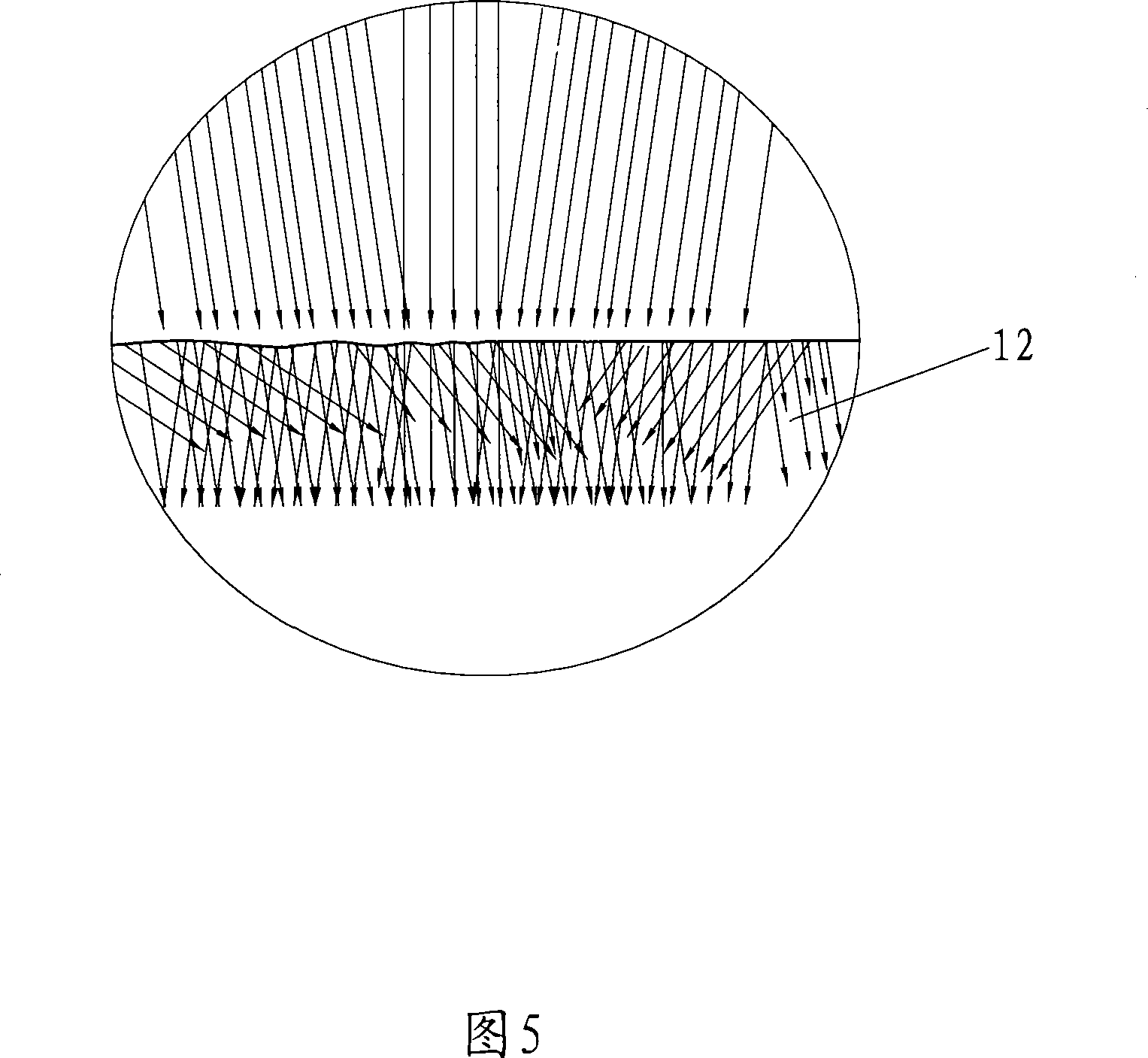
[0023] As shown in Figures 1 to 7, the solar cell chip protection structure of the present invention is provided with a concentrating mirror 1 on the upper part of the solar cell chip 2, wherein: the concentrating mirror 1 is provided with a light-transmitting area 11 at a position corresponding to the size of the cell chip 2, On the outer edge of the light-transmitting area 11 of the condenser 1 is a light-reflecting area 12 .

[0024] The size of the light-transmitting area 11 just corresponds to the size of the battery chip 2, so the battery chip 2 can effectively collect sunlight; in addition, the unused concentrated light outside the solar chip 2 is reflected or absorbed by the light-reflecting area 12 so as not to irradiate the PCB board , causing the temperature rise to melt or crack the PCB board, thereby effectively prolonging the service life of the solar cell.

[0025] As shown in Fig. 1, 2 is embodiment 1 of the present invention, and this concentrating mirror 1 is...


PUM


Abstract

The present invention provides a solar cell chip protecting structure, the top of the battery cell is arranged with a beam condenser, wherein the position corresponding to the magnitude of the cell chip on the beam condenser is arranged with a light-permeating area, the outer margin of the light-permeating area of the beam condenser is a light reflecting area; and the light-permeating area is obscured glass or toroidal lens. When the magnitude of the light-permeating area is just corresponding to the magnitude of the chip, the chip can effectively collect the sun ray; additionally the collected light which excepts the solar chip and needs not be utilized is reflected by the reflecting area or absorbed for avoiding the irradiating to the PCB board and causing the temperature raising and leading to the melting or rupture of the PCB board thereby effectively prolonging the service lifetime of the solar battery; and the light-permeating area is executed with matte surface treatment or is arranged to an optical toroidal lens can lead to that the light irradiating into the chip is rearranged through the scattered reflection or reflection/refraction of the toroidal lens, for uniformly arranging the light emitting to the chip, increasing the filling factor of the solar cell chip, overcoming the disadvantage of the light-focusing solar battery, sufficiently exerting the predominance and greatly increasing the effective utilization rate of the solar cell.

Description

technical field [0001] The invention belongs to the field of solar energy, in particular to a solar cell chip protection structure. Background technique [0002] A solar cell is a device that directly converts solar energy into electrical energy due to the photovoltaic effect. When the sun shines on the solar cell, it will convert the sun's light energy into electrical energy and generate electric current. When multiple solar cells are connected in series or in parallel, it can become a solar cell matrix with large output power. Solar cells are a promising new energy source with three advantages of durability, cleanliness and flexibility. Solar cells have a long lifespan. As long as sunlight exists, solar cells can be used for a long time with one investment; compared with thermal power generation and nuclear power generation, solar energy itself is an environmentally friendly green energy that will not cause environmental pollution; solar cells can be large, medium and sm...

Claims


Application Information

Patent Timeline
IPC IPC(8): H01L31/052H01L31/0232
CPCY02E10/52H01L31/0522H01L31/0236H01L31/054H01L31/048Y02E10/50
Inventor 王水菊万学超陈天庆
Owner GENIUS ELECTRONICS OPTICAL XIAMEN
Why Eureka
Try Eureka