
Non-stirring oxidization device of flue gas desulfurization slurry pool

A desulfurization slurry and oxidation device technology, which is applied to chemical instruments and methods, separation methods, and dispersed particle separation, can solve problems such as easy failures and complex structures, and achieve the effect of improving desulfurization efficiency and eliminating the need for stirring devices

Inactive Publication Date: 2008-08-20
CPI YUANDA ENVIRONMENTAL PROTECTION ENG +1
View PDF2 Cites 9 Cited by
  • Summary
  • Abstract
  • Description
  • Claims
  • Application Information

AI Technical Summary

Problems solved by technology

In the above two patents, there is a stirrer, which is driven by a high-power motor. The stirrer is equipped with a stirring impeller. The structure is relatively complicated, and it is prone to failure, and the deposits on the impeller must be cleaned regularly.

Method used


Image

  • Non-stirring oxidization device of flue gas desulfurization slurry pool
  • Non-stirring oxidization device of flue gas desulfurization slurry pool
  • Non-stirring oxidization device of flue gas desulfurization slurry pool

Examples


Embodiment 1

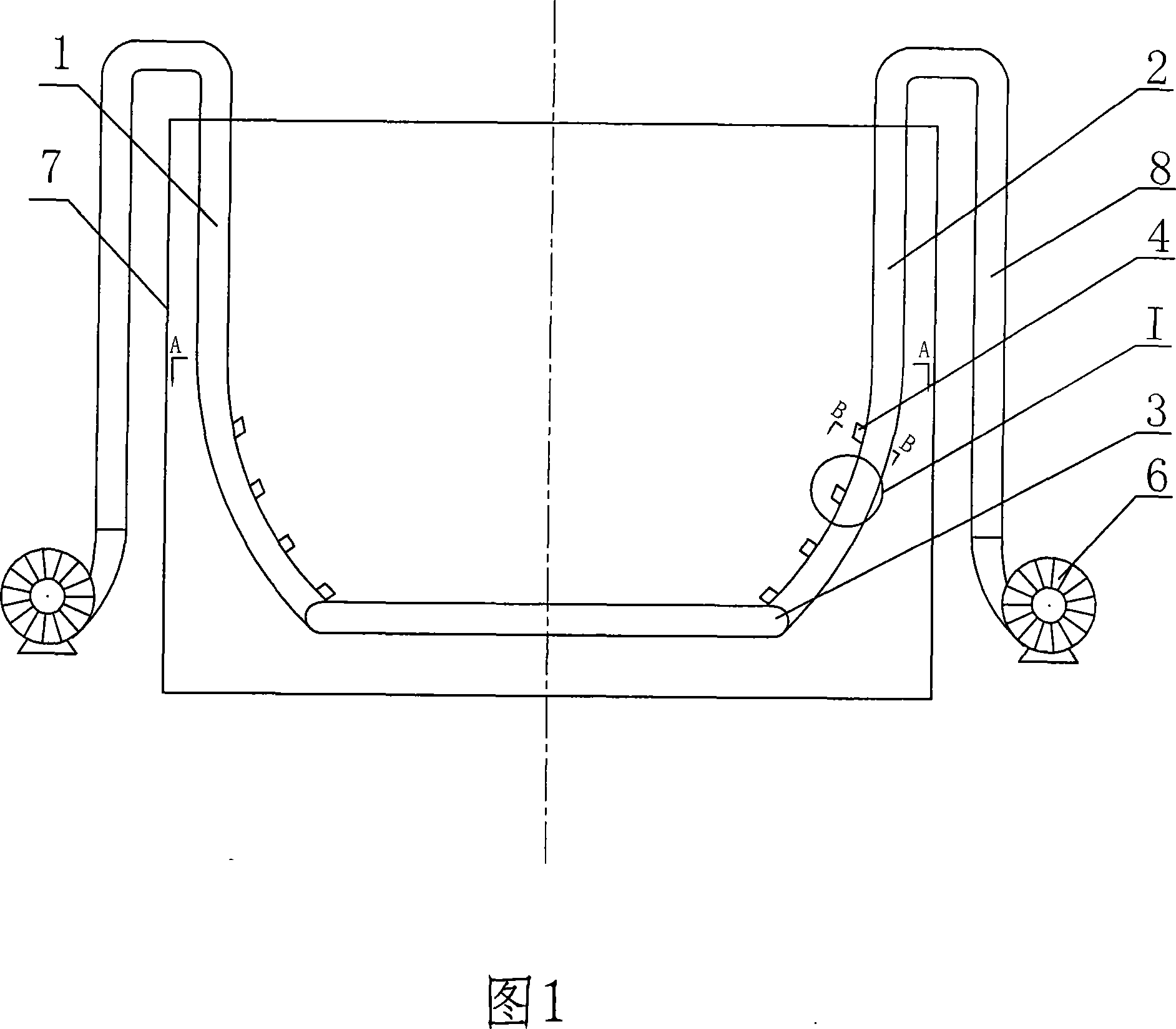
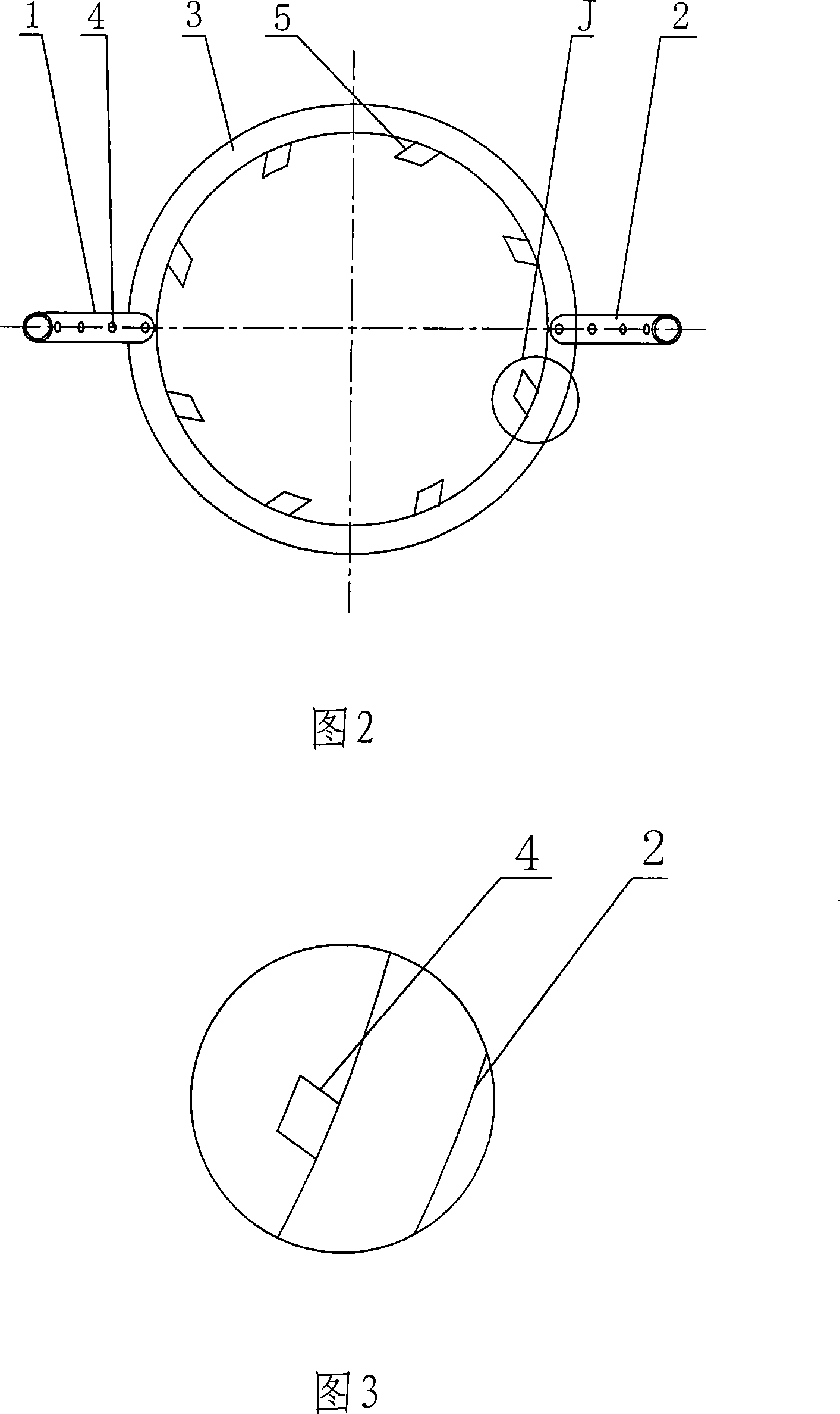
[0016] Embodiment 1, as shown in Figure 1 and Figure 2, the present invention is mainly made up of slurry pool 7, circular conduit 3, arc conduit 1,2 and air compressor 6, and circular conduit 3 is installed in the bottom of slurry pool 7 The two ends of a diameter of the circular conduit 3 are provided with a first arc conduit 1 and a second arc conduit 2, and the lower ends of the first arc conduit 1 and the second arc conduit 2 communicate with the circular conduit 3, The upper end protrudes from the slurry tank 7 and is connected with the output end of the air compressor 6 through an external connecting pipe 8 .

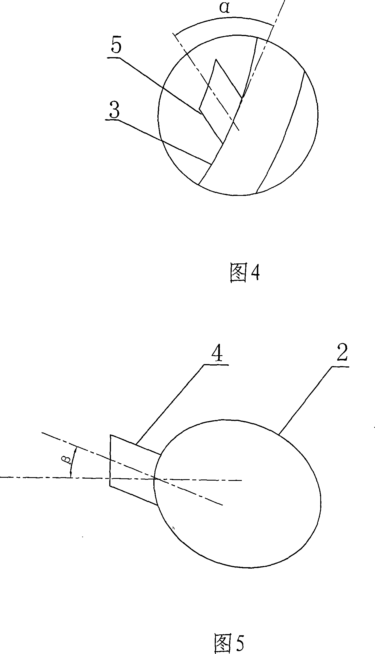
[0017] Further as shown in Fig. 3, Fig. 4 and Fig. 5, on the inner ring of described circular conduit 3, be welded with 8 lower jet tubes 5, the center line of this lower jet tube 5 and pass through this center line and circular duct 3 The tangent of the intersection point is an acute angle α. When α is 1 degree, the swirl velocity formed by the air ejected from ...

Embodiment 2

[0018] Embodiment 2, as shown in Figure 6, a first arc-shaped conduit 1, a second arc-shaped conduit 2, a third arc-shaped conduit 9 and a fourth The arc conduit 10, other structures are the same as that of embodiment 1, and four arc conduits blow compressed air into the slurry pool 7, so that the slurry is stirred more evenly, which is more conducive to the oxidation reaction. When the volume of the slurry pool is large, it needs For greater stirring kinetic energy, the number of curved conduits can continue to be increased.

[0019] At the same time, the present invention can also use the self-priming pump to introduce the mixture of air and slurry, thereby obtaining greater driving force.


PUM


Abstract

The invention relates to an oxidation unit for the flue gas desulfurization, in particular to a non-stirring oxidation unit used in a flue gas desulfurization slurry pool. A circular pipe is arranged in the lower part of the slurry pool; a plurality of arc pipes are arranged at both ends of at least a diameter of the circular pipe; the lower end of the arc pipe is connected with the circular pipe; the upper end of the arc pipe extends out of the slurry pool and is connected with the output of an air compressor 6 through an outer connecting hose; a gas ejector pipe is arranged on the inner ring of the circular pipe; the lower part of the arc pipe is arc-shaped; and two upper gas ejector pipes are respectively and oppositely arranged on the pipe wall of the arc part of the two arc pipes. The oxidation unit has the advantages that the air required for oxidation is ejected from the gas ejector pipes after compressed in order to enable the slurry in the slurry pool to flow and form swirling so as to reach the purpose of stirring the calcium sulfite and save the stirring device; and the air utilized for stirring is benefit to the sufficient contact between the oxygen and the calcium sulfite so as to increase the desulfuration efficiency.

Description

technical field [0001] The invention relates to a flue gas desulfurization device, in particular to a non-stirring oxidation device for a slurry tank of flue gas desulfurization. Background technique [0002] With the rapid and sustained economic development, the atmosphere is being destroyed by SO 2 The pollution situation is getting more and more serious. Flue gas desulfurization (FGD) of coal-fired boilers is currently the only 2 The way of emission, in this technology, limestone-gypsum wet flue gas desulfurization (WFGD) occupies a dominant position. In WFGD, there are currently two main technologies, one is liquid column technology and the other is spray tower technology. The two technologies are distinguished by different types of desulfurization towers. [0003] In the limestone-gypsum wet flue gas desulfurization process, the oxidation of calcium sulfite is an important chemical process, and its oxidation efficiency is directly related to the SO 2 Therefore, impr...

Claims


Application Information

Patent Timeline
IPC IPC(8): B01D53/80B01D53/50
Inventor 杨剑杜云贵刘清才刘艺董凌燕隋建才李锋洪燕王方群王强孙卫魏春梅
Owner CPI YUANDA ENVIRONMENTAL PROTECTION ENG
Learn More