
Ejection air-supplying turbosupercharger

A turbocharger and ejector technology, which is applied in the direction of machines/engines, engine components, internal combustion piston engines, etc., can solve the problem of increasing capacity, volume, investment and energy consumption, and failing to play the role of jet ejection and air replenishment , high-pressure jet air inflow momentum and other problems, to achieve the effect of convenient regulation, simple structure and fast response

Inactive Publication Date: 2008-08-20
孙敏超 +1
View PDF1 Cites 26 Cited by
  • Summary
  • Abstract
  • Description
  • Claims
  • Application Information

AI Technical Summary

Problems solved by technology

Compared with the variable geometry cross-section adjustable turbocharger scheme that mechanically rotates the nozzle vane or the tongue-shaped baffle to change the installation angle, this scheme has the advantages of strong regulation, simple structure, low cost, high efficiency, safety and reliability, and convenient regulation. And it can be applied to gasoline engine turbocharging and other advantages, and its disadvantage is that it generally needs to increase the external high-pressure air source device
Another shortcoming of this scheme is: its structure of introducing external source high-pressure compressed air assembly makes the inflow momentum value of high-pressure jet air very low (high-pressure air is introduced into turbine nozzle blade ring air chamber or bladeless worm by external air source The inlet of the shell is almost entirely dependent on the static pressure difference, and the flow rate is not high), and the jet ejection effect of the high-pressure air obtained by using the high-speed airflow cannot be exerted, resulting in a significant increase in the amount of high-pressure air consumed to achieve the same boost pressure. It also increases the capacity, volume, investment and energy consumption of high-pressure air source equipment accordingly

Method used


Image

  • Ejection air-supplying turbosupercharger
  • Ejection air-supplying turbosupercharger
  • Ejection air-supplying turbosupercharger

Examples


Embodiment Construction

[0028] Hereinafter, the technical content of the present invention will be further described through the embodiments and in conjunction with the accompanying drawings.

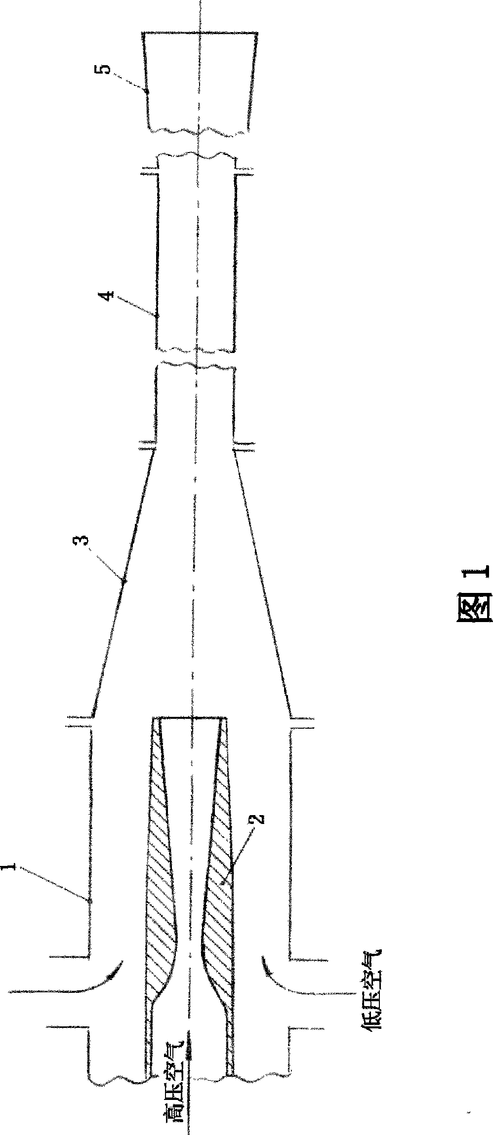
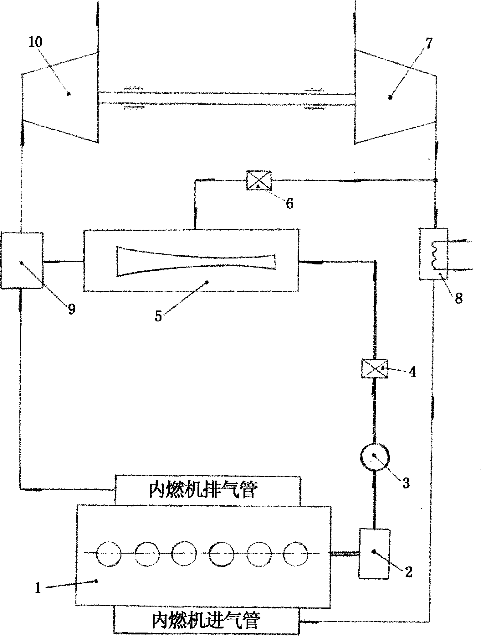
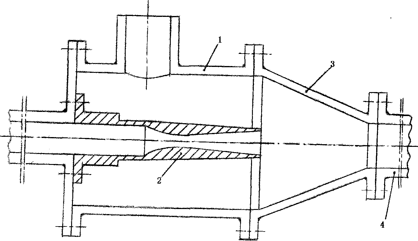
[0029] As mentioned above, the technical core of the present invention is to use the high-pressure compressed air flowing out from the air storage tank of the external source compressed air supply device, and the high-speed jet air formed by its expansion acceleration in the nozzle pipe of the gas ejector to induce The low-pressure pressurized air injected into the cylinder of the gas ejector by bypassing the compressor outlet of the turbocharger, the two are mixed in the mixing section of the ejector and boosted by the diffuser to form "supplementary air". Introduced into the guide pipe installed in the box-shaped air supply chamber between the outlet flange of the exhaust pipe of the internal combustion engine and the inlet flange of the turbine volute of the turbocharger, and finally near the outlet of the a...


PUM


Abstract

The invention discloses a turbocharger which utilizes the outer source compressed air to apply complementary energies on a rotor of the turbocharger, so as to improve the pressurizing pressure and improve the lower working situation property and instant characteristics of a gas engine. The turbocharger is formed by combining three parts of a turbocharger with ordinary structure and two accessories - a gas ejector and a gas complementing chamber. The outer source high-pressure compressed air ejects partial low-pressure pressurizing air through the gas ejector to form gas complementing air to flow in the gas complementing chamber to be mixed with the exhaust gas of the gas engine, thus increasing the fuel gas flow flowing into a turbine and improving the power and pressurizing pressure of the turbine. Compared with the prior art, the turbocharger has the advantages of mature technology, simple structure, reliable and safe use, low cost, direction pressure control, large adjusting and controlling degree, fast response and good effect; besides, the turbocharger can ensure the working situation to operate continuously after being adjusted and controlled and can be used on the gas engines of vehicles, ships and engineering plants.

Description

technical field [0001] The invention relates to turbochargers in the technical field of internal combustion engine supercharging Background technique [0002] Internal combustion engine turbocharging is the combined operation of a turbocharger of a rotary impeller machine and an internal combustion engine of a reciprocating piston machine. Due to the different working characteristics of these two machines, it is inevitable that the joint work that originally achieved a good match in a certain working condition parameter will cause many incompatible problems in matching when the working condition parameter changes. Among them, how to improve the low working conditions (low speed, low load performance) and transient characteristics (acceleration) of high-pressure internal combustion engines is the most eye-catching. During the development process of internal combustion engine turbocharging technology, which constantly pursues high mean effective pressure and correspondingly i...

Claims


Application Information

Patent Timeline
IPC IPC(8): F01D17/00F02B37/12
CPCY02T10/144Y02T10/12
Inventor 孙敏超孙正柱
Owner 孙敏超
Learn More