Damper
A damper and damping cavity technology, applied in the direction of shock absorbers, shock absorbers, liquid shock absorbers, etc., can solve the problems of large starting resistance, high heating temperature, damper damage, etc., and achieve low starting resistance and simple structure. , the effect of stable performance
- Summary
- Abstract
- Description
- Claims
- Application Information
AI Technical Summary
Problems solved by technology
Method used
Image
Examples
Embodiment 1
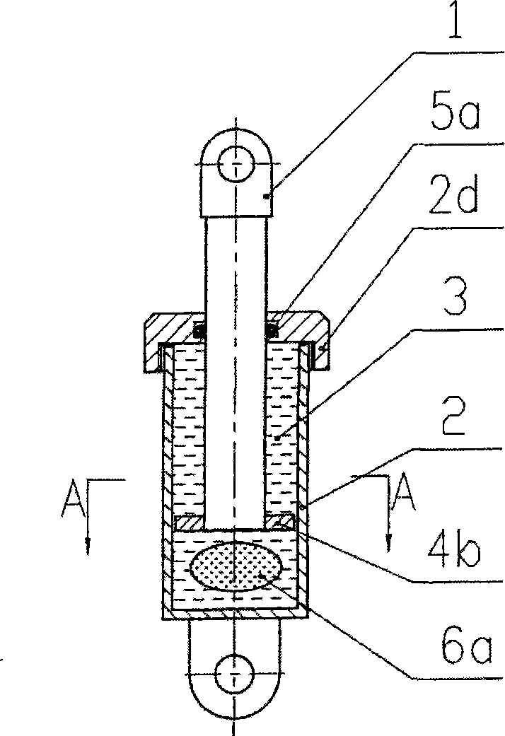
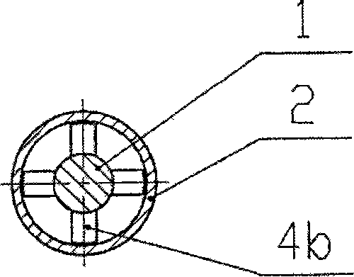
[0036] see figure 1 , 2 , which includes a moving body 1 and a cylinder body 2. The moving body 1 is partially located in the cylindrical cylinder body 2 and can move axially relative to the cylinder body 2. A damping chamber extending axially is arranged in the cylinder body. The damping chamber is filled with a viscous damping liquid 3, which is modified emulsified asphalt in a viscous liquid state at normal temperature. The moving body 1 is composed of a cylindrical moving blade, which is located in the damping chamber and connected with the damping chamber The walls form a shear cavity whose radial dimension is much smaller than its axial dimension. The end of the cylinder block is provided with a cylinder head 2d, the cylinder head cooperates with the sliding guide of the moving blade, the cylinder head is embedded with a sliding sealing ring 5a, and the end of the moving blade is fixed with a sliding guide block 4b, which is in the shape of a cross, allowing the damping...
Embodiment 2
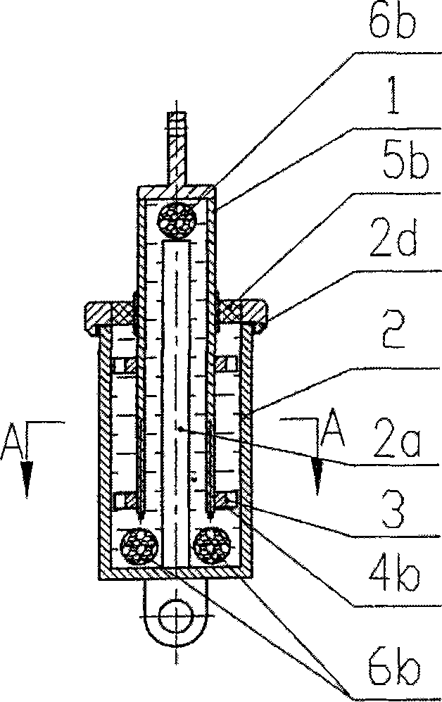
[0040] See attached image 3 , 4 , compared with Embodiment 1, a cylindrical stationary vane 2a is provided in the center of the cylinder body 2, and the damping chamber is changed into an annular damping chamber. Correspondingly, the moving blade of the moving body 1 is tubular, and the moving blade is located in the damping chamber In the chamber, the shear chamber is formed with the wall of the damping chamber and the stationary vane 2a. The damping chamber and the shearing chamber are filled with methyl silicone oil. The transverse dimension of the shearing chamber is much smaller than its axial dimension. The lower part of the damping chamber is There is a ring-shaped elastic compensator 6b. The elastic compensator 6b is provided in the damping chamber on the top of the movable body. The elastic compensator 6b is an elastic foamed polyurethane with an airtight elastic layer on the outside.
[0041] Compared with Example 1, the moving blade of this embodiment has two visc...
Embodiment 3
[0046] See attached Figure 7 , 8 , compared with embodiment 2, the stationary blade in the damping chamber in the cylinder body 2 is a garden tubular shape 2c, and the moving body 1 is composed of 2 circular tubular moving blades, forming 3 concentric shearing chambers, and the damping chamber The lower part is provided with an annular elastic compensation body 6b, and the elastic compensation body is an elastic foamed polyurethane with an airtight elastic layer on the outside. There is a compensation chamber on the top of the moving body, and an airtight elastic film 6c is arranged in the compensation chamber, one side of which is filled with compressed air, and the other side is filled with damping liquid, which communicates with the damping chamber to compensate for the volume change of the damping chamber ; In order to increase the viscous resistance, the end of the inner moving blade is also provided with a flanging type spoiler ring piece.
[0047] In this embodiment,...
PUM
 Abstract
Description
Claims
Application Information
 - R&D
- Intellectual Property
- Life Sciences
- Materials
- Tech Scout
- Unparalleled Data Quality
- Higher Quality Content
- 60% Fewer Hallucinations
Browse by: Latest US Patents, China's latest patents, Technical Efficacy Thesaurus, Application Domain, Technology Topic, Popular Technical Reports.
© 2025 PatSnap. All rights reserved.Legal|Privacy policy|Modern Slavery Act Transparency Statement|Sitemap|About US| Contact US: help@patsnap.com


