Induction heating power supply circuit

A technology of induction heating power supply and circuit, used in induction heating, induction current source, induction heating control and other directions

Inactive Publication Date: 2008-08-20
俞正国
View PDF0 Cites 12 Cited by
  • Summary
  • Abstract
  • Description
  • Claims
  • Application Information

AI Technical Summary

Problems solved by technology

For example, the patent application numbers are 200610149995.3, 200520100520.6, 200510041878.0, etc., but they are all l...

Method used


Image

  • Induction heating power supply circuit
  • Induction heating power supply circuit
  • Induction heating power supply circuit

Examples


Embodiment 1

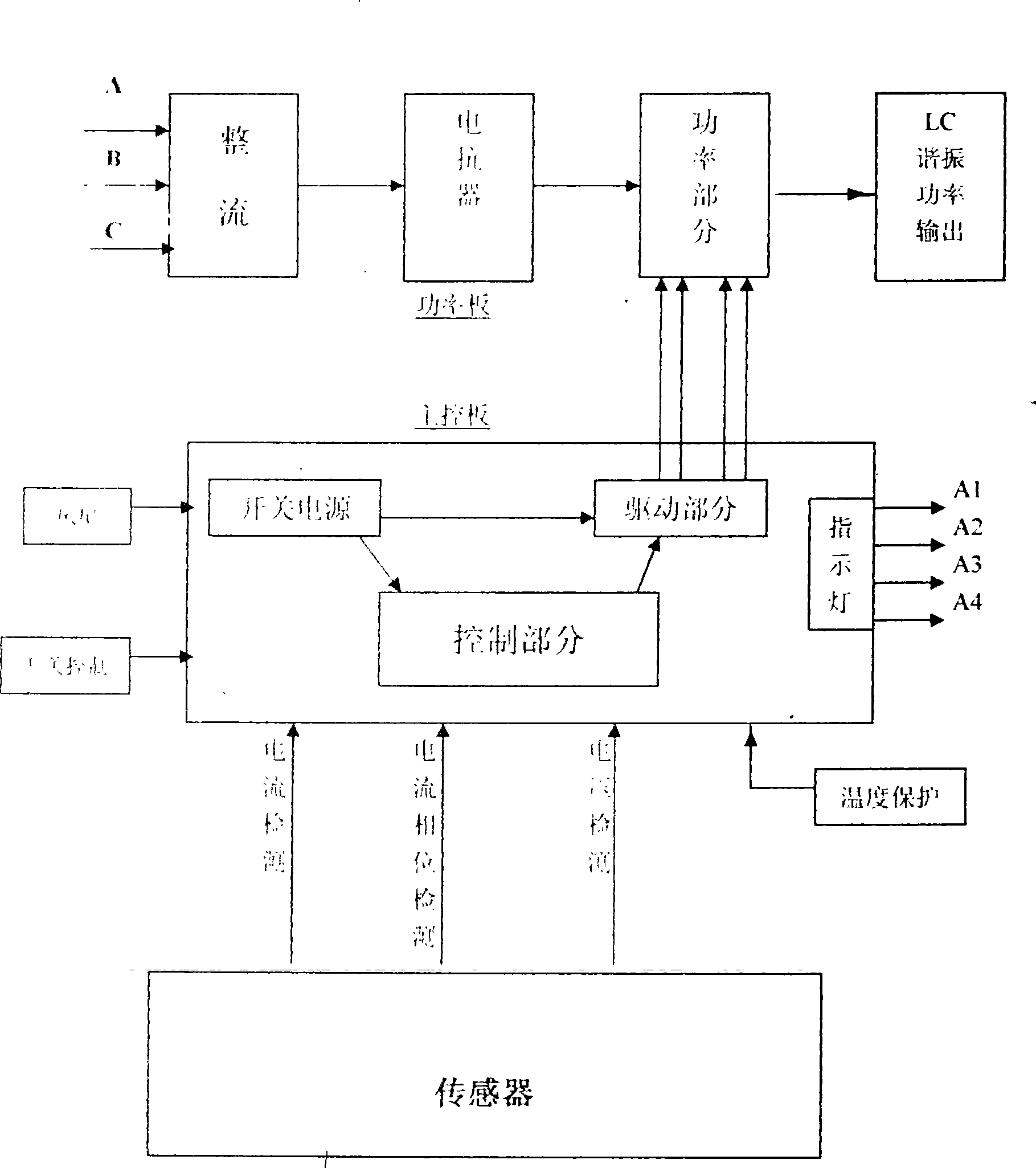
[0052] Please refer to the views, this embodiment is composed of a main control circuit part and a power circuit part.

[0053] 1. Main control part:

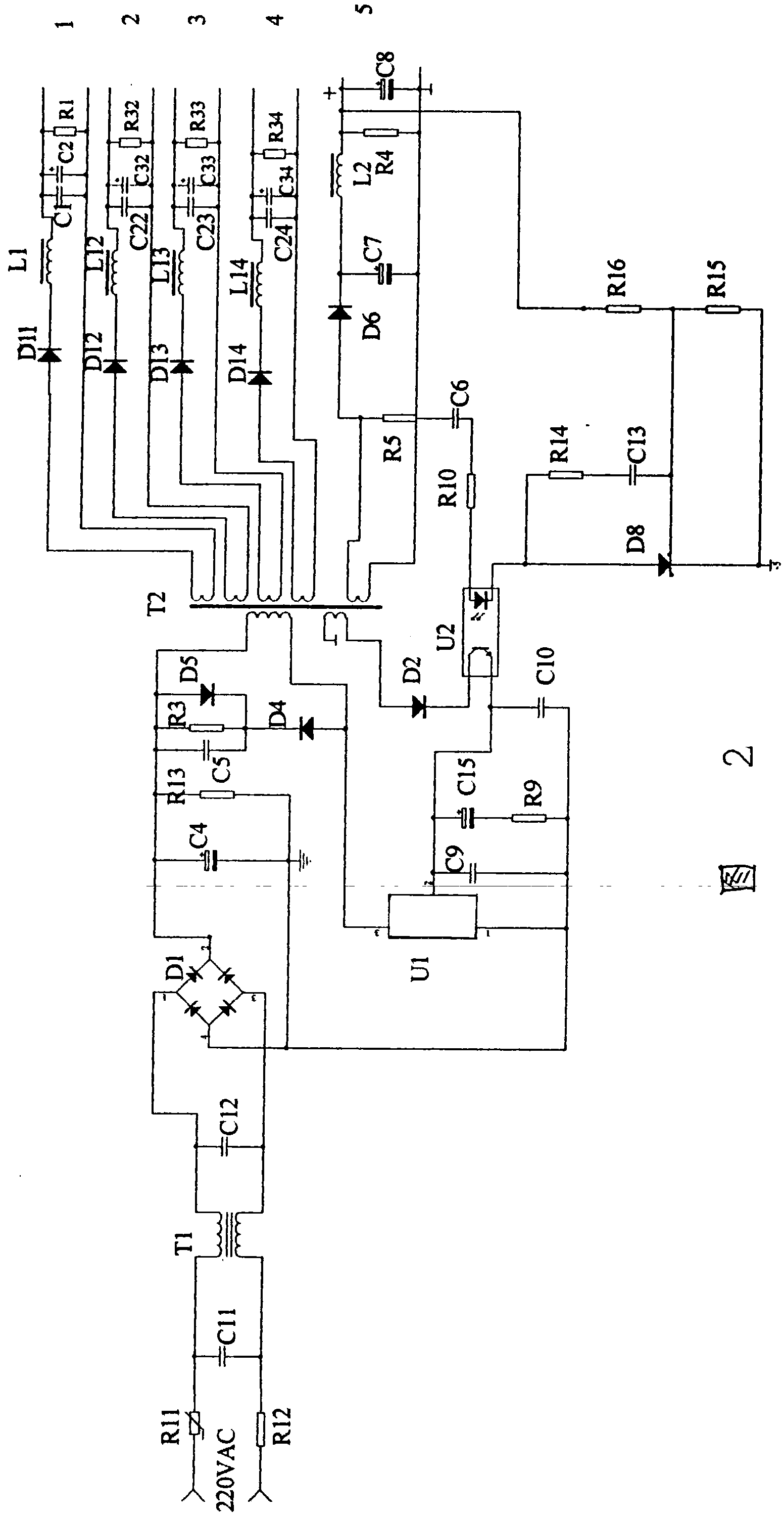
[0054] ①Switching power supply and drive part:

[0055]Mains AC 220V is connected to both ends of capacitor C11 and common mode inductor T1 through temperature insurance R12 and negative temperature coefficient thermistor R11, and the other two ends of common mode inductor are connected to both ends of capacitor C12 to filter out common After mode interference and differential mode interference, it is connected to the AC input terminal of rectifier bridge B for rectification. The output + of the rectifier bridge is connected to the '+' of the electrolytic capacitor C4, and the '-' of the rectifier bridge B is connected to the '-' of the electrolytic capacitor C4. The phase is connected to the hot ground for filtering, the resistor R3 is connected to the two ends of the electrolytic capacitor C4, the capacitor C5, the resistor ...


PUM


Abstract

The invention discloses an induction heating power circuit which belongs to electric product field. The induction heating power circuit is composed of a main-control part and a power part. The main-control part comprises switch electrical source and drive part, oscillation excitation part, phase and voltage locking, load too-small detection, load too-large detection, voltage limitation protection, current limitation protection, soft start part, temperature protection part; the power part comprises sensor and core part composed of full bridge power tube. The induction heating power circuit uses four wire three phase output method, the heating electrical source operation is in safe and high-efficient method by processing reactive power compensation and harmonic management through reactor after rectification, accordingly, various hidden dangers of traditional resistance wire heating method is avoided. The induction heating power circuit can be wide used in plastic film blower, wire drawing machine, injection molding machine, granulator, rubber extruder, curing press, cable extruder, petroleum heating and bathroom heating in daily life etc.

Description

technical field [0001] The invention relates to electrical products, in particular to an induction heating power supply circuit. Background technique [0002] The traditional heating power supply uses the heating method of resistance wire, and its thermal efficiency is very low. This heating method mainly relies on contact conduction to transfer heat energy. For various heating plates or heating rings made of resistance wire, only one surface needs to be heated. In the part of the air, a large part of the heat energy is dissipated in the air, which not only causes the loss of energy, but also because the resistance directly contacts the heated body, it may cause leakage and cause casualties. Because the resistance wire heating itself will generate heat, not only It is easy to be damaged and the maintenance cost is high, and it may cause fire and cause unnecessary economic losses. [0003] Retrieval from relevant materials including Chinese patents shows that there are some ...

Claims


Application Information

Patent Timeline
IPC IPC(8): H05B6/06H05B6/04
Inventor 俞正国
Owner 俞正国
Why Eureka
Try Eureka