Fluid control apparatus

A fluid control device and fluid control valve technology, applied in fluid pressure control, valve device, flow control using electrical devices, etc., can solve problems such as uncomfortable flow control, complicated operation and time-consuming, and insufficient flow range.

Inactive Publication Date: 2008-08-20
ASAHI YUKIZAI KOGYO CO LTD
View PDF5 Cites 9 Cited by
  • Summary
  • Abstract
  • Description
  • Claims
  • Application Information

AI Technical Summary

Problems solved by technology

[0005] However, the above-mentioned existing pure water flow control device 301 balances the output pressure of the pure water in the flow regulating valve 302, thereby controlling the pure water flow output from the flow regulating valve 302 to be constant. Therefore, it is not suitable for The flow rate is finely controlled, and the flow range is not wide enough, so there is a problem that it is difficult to control the flow rate in a wide flow range
In addition, since there are many components, when installing them in semiconductor manufacturing equipment, etc., it is necessary to perform piping connection work, electric wiring, and air piping work for each component separately, and the work is complicated and time-consuming, and the piping and wiring may be complicated. error occurred
[0006] In addition, in the above-mentioned conventional flow control assembly 306, when the fluid flowing into the fluid control device is a pulsating fluid with a short pressure fluctuation period, there is a problem that although the control valve 308 intends to perform flow control on the pulsating fluid, However, it will cause oscillation and fluid control cannot be performed. If it continues, there will be a problem that the driver 311 and the control valve 308 may be damaged.
In addition, since the flow range for flow control is not wide, there is a problem that it is difficult to use for flow control in a large flow range.

Method used


Image

  • Fluid control apparatus
  • Fluid control apparatus
  • Fluid control apparatus

Examples


Embodiment 1

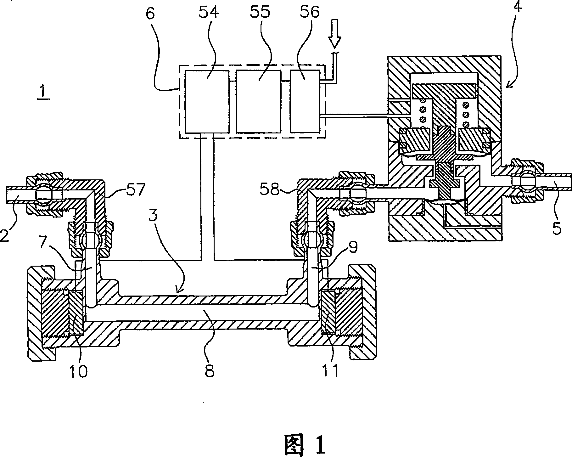
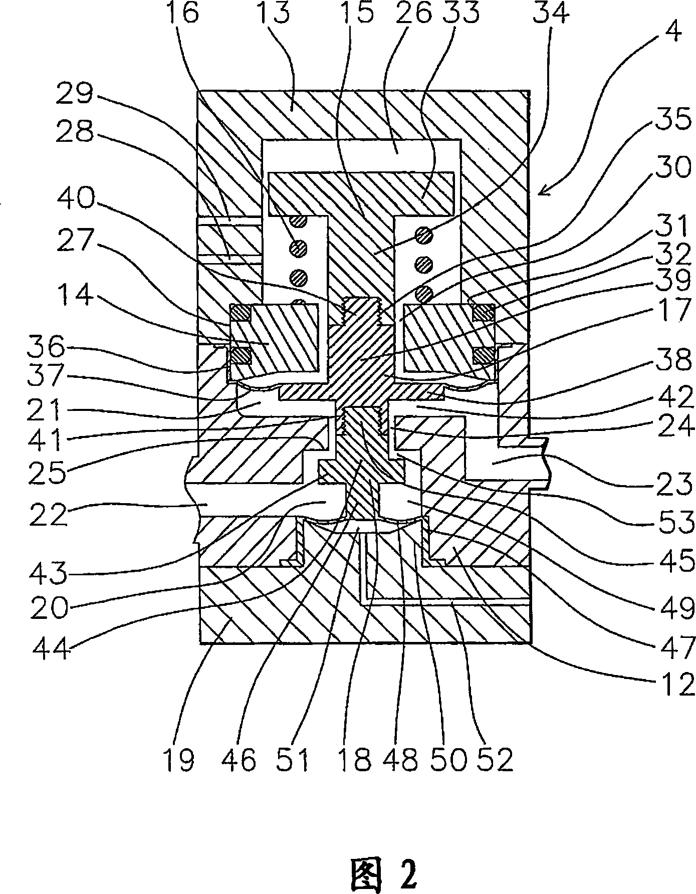
[0075] Hereinafter, a fluid control device as a first embodiment of the present invention will be described based on FIGS. 1 and 2.

[0076] 1 is a fluid control device installed in a semiconductor manufacturing device that performs an etching process of semiconductor manufacturing. The fluid control device 1 includes a fluid inflow port 2, a flow rate measuring device 3, a fluid control valve 4, a fluid outflow port 5, and a control unit 6, and their respective configurations are as follows.

[0077] 2 is a fluid inlet made of PFA. The fluid inflow port 2 is in communication with the inlet flow path 7 of the flow rate measuring device 3 described later.

[0078] 3 is a flow meter that measures the flow rate of the fluid. The flow meter 3 has: an inlet flow path 7, a straight flow path 8 arranged perpendicularly from the inlet flow path 7, and an outlet flow path 9 arranged perpendicularly from the straight flow path 8 and arranged in parallel with the inlet flow path 7 in the sam...

Embodiment 2

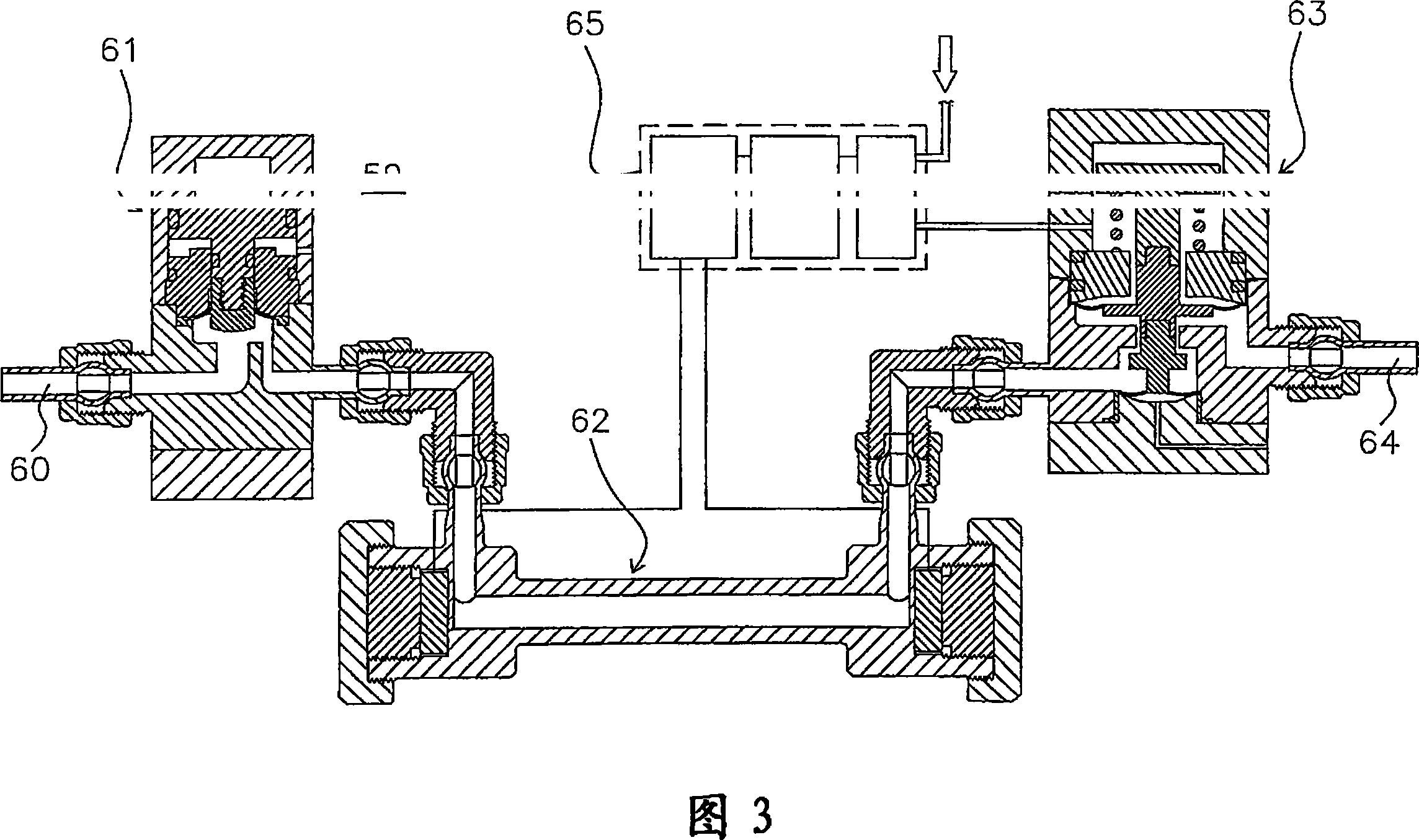
[0100] Next, a fluid control device as a second embodiment of the present invention will be described based on FIGS. 3 and 4.

[0101] 59 is a fluid control device. The fluid control device 59 includes a fluid inflow port 60, an on-off valve 61, a flow rate measuring device 62, a fluid control valve 63, a fluid outflow port 64, and a control unit 65, and their respective configurations are as follows.

[0102] 61 is an on-off valve. The on-off valve 61 includes a main body 66, a driving part 67, a piston 68, a diaphragm pressure member 69, and a valve core 70.

[0103] 66 is a body made of PTEF. It has a valve chamber 71 at the center of the upper end in the axial direction, and has an inlet flow path 72 and an outlet flow path 73 communicating with the valve chamber 71. The inlet flow path 72 communicates with the fluid inlet 60, and the outlet flow path 73 communicates with the flow meter 62. In addition, an annular groove 74 is provided outside the valve chamber 71 on the upper...

Embodiment 3

[0114] Next, a fluid control device as a third embodiment of the present invention will be described based on FIGS. 5 to 9.

[0115] 81 is a fluid control device. The fluid control device 81 includes a fluid inflow port 82, a flow rate measuring device 83, a fluid control valve 84, a throttle valve 85, a fluid outflow port 86, and a control unit 87, and their respective configurations are as follows.

[0116] 85 is a throttle valve with adjustable opening area. The throttle valve 85 includes a main body 88, a diaphragm 97, a second valve stem 106, a diaphragm pressing member 108, a first valve stem 114, a first valve stem support body 121, and a valve cover 125.

[0117] 88 is the main body made of PTFE. On the upper part of the main body 88 there is a valve chamber 90 having a substantially mortar shape formed with the following diaphragm 97, and on the bottom surface of the valve chamber 90 is formed a valve that performs a fully closed sealing of the flow path by pressing the s...


PUM


Abstract

A fluid control apparatus is provided with a fluid control valve for controlling the pressure of a fluid by pressure operation of a fluid for control; a flow volume measuring apparatus for measuring the flow volume of the fluid, converting the measured value of the flow volume into electric signals and outputting the signals; and a control section for outputting a command signal for controlling an opening area of the fluid control valve to the fluid control valve or to an apparatus which operates the fluid control valve, based on a deviation of the electric signal from a set flow volume outputted from the flow volume measuring apparatus.

Description

Technical field [0001] The present invention relates to a fluid control device used in a fluid delivery piping that requires fluid control. In more detail, it involves easy installation, piping, and wiring connections mainly in semiconductor manufacturing equipment. Even if pulsating fluid flows through, the flow rate can be controlled without any problems, and the flow rate can be finely performed in a large flow rate range. Controlled fluid control device. Background technique [0002] Conventionally, as one step of the semiconductor manufacturing process, wet etching in which the surface of the wafer is etched using washing water obtained by diluting a chemical liquid such as hydrofluoric acid with pure water. It is necessary to control the concentration of the washing water of these wet etching with high accuracy. In recent years, a method of managing the concentration of washing water based on the flow ratio of pure water and chemical liquid has become mainstream. Therefore,...

Claims


Application Information

Patent Timeline
Patent Type & Authority Applications(China)
IPC IPC(8): G05D7/06F16K31/126F16K41/12
CPCG05D16/185F16K31/402F16K41/12F16K31/1264Y10T137/7761F16K31/1221
Inventor 吉野研郎上村忍文
Owner ASAHI YUKIZAI KOGYO CO LTD
Why Eureka
Try Eureka