Enclosed type electrolytic tank and electrolytic system

An electrolytic cell and closed technology, applied in the field of electrolytic cells, can solve the problems of uneven electrode current distribution, poor operating environment of electrolysis workshop, and increase the chance of side reactions, achieve good electrode potential distribution, and reduce the chance of side reactions. , the effect of increasing the limiting current density

Active Publication Date: 2008-08-27
BEIJING GENERAL RES INST OF MINING & METALLURGY
View PDF0 Cites 15 Cited by
  • Summary
  • Abstract
  • Description
  • Claims
  • Application Information

AI Technical Summary

Problems solved by technology

[0002] In the existing production technology, the general-purpose electrolytic cell is an open electrolytic cell. Due to the slow flow rate of the electrolyte, it is difficult to ensure a uniform flow rate of the liquid, and it is prone to uneven flow and dead ends, which not only makes the current distribution on the electrodes uneven , causing the electrolytic current density to drop, and because the flow rate is slow, the laminar layer on the electrode surface is wider, so that the concentration of the electrolyte on the plate surface becomes lower, resulting in concentration polarization, the cell voltage rises, and the secondary The chance of reaction occurs, thus limiting the increase of current density during electrolysis; in electrolysis engineering, the electrolytic cell is the key to investment, especially the area of ​​the electrode leads to an increase in the cost of the electrolytic cell, so in the case of ensuring a certain scale of equipment, increase the unit Reducing the electrode area is the key to reducing investment; in addition, the existing electrolytic cell is open, and the gas generated during electrolysis will entrain the electrolyte and volatilize into the plant, resulting in a poor operating environment for the electrolytic plant

Method used


Image

  • Enclosed type electrolytic tank and electrolytic system
  • Enclosed type electrolytic tank and electrolytic system
  • Enclosed type electrolytic tank and electrolytic system

Examples


Embodiment 1

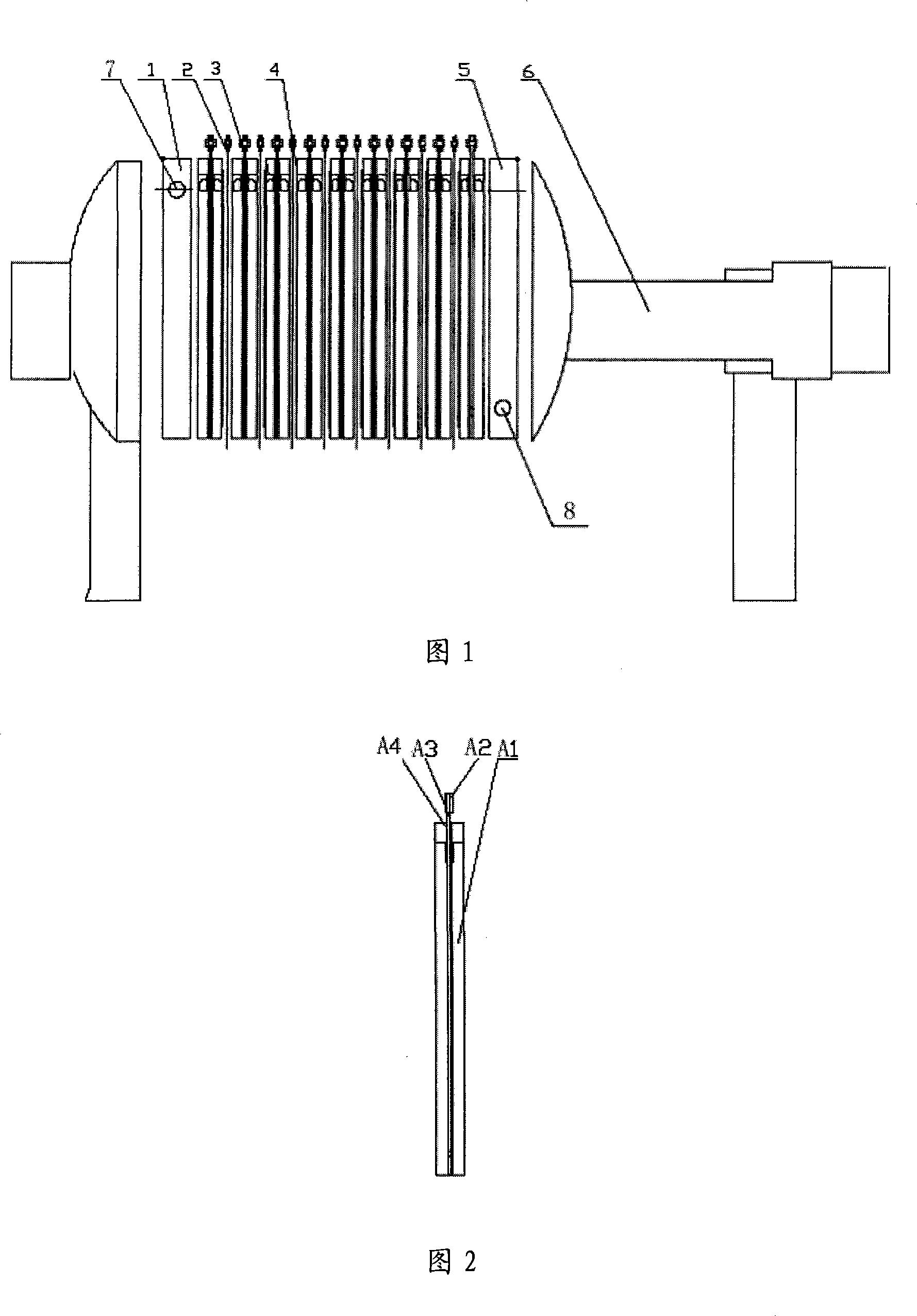
[0029] As shown in FIG. 1, an embodiment of the present invention provides a closed electrolytic cell, which is specifically used for electrowinning various metals, including:

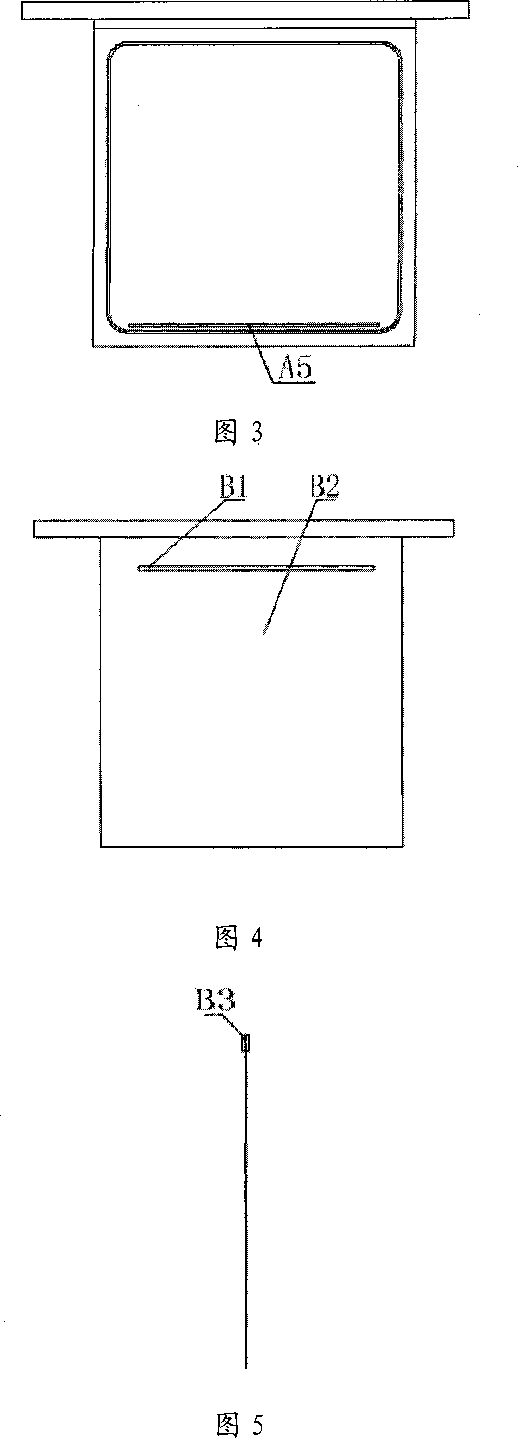
[0030] Two end plates 1, 5, anode assembly 3, cathode assembly 2, seal 4 and pressing device 6; two end plates 1, 5 are provided with liquid flow ports 7, 8, anode assembly 3 and cathode assembly 2 There is a flow through hole correspondingly on the upper part, the anode assembly 3 and the cathode assembly 2 are arranged at intervals between the two end plates 1 and 5, and a pole chamber is formed between the adjacent anode assembly and the cathode assembly. A plurality of anode assemblies and cathode assemblies are arranged, so that a plurality of electrode chambers can be formed, and the distance between the plates of the anode assemblies and the cathode assemblies can be set in the range of 20-100 mm. The anode assembly 3, the cathode assembly 2 and the end plates 1 and 5 are all provided with seals...

Embodiment 2

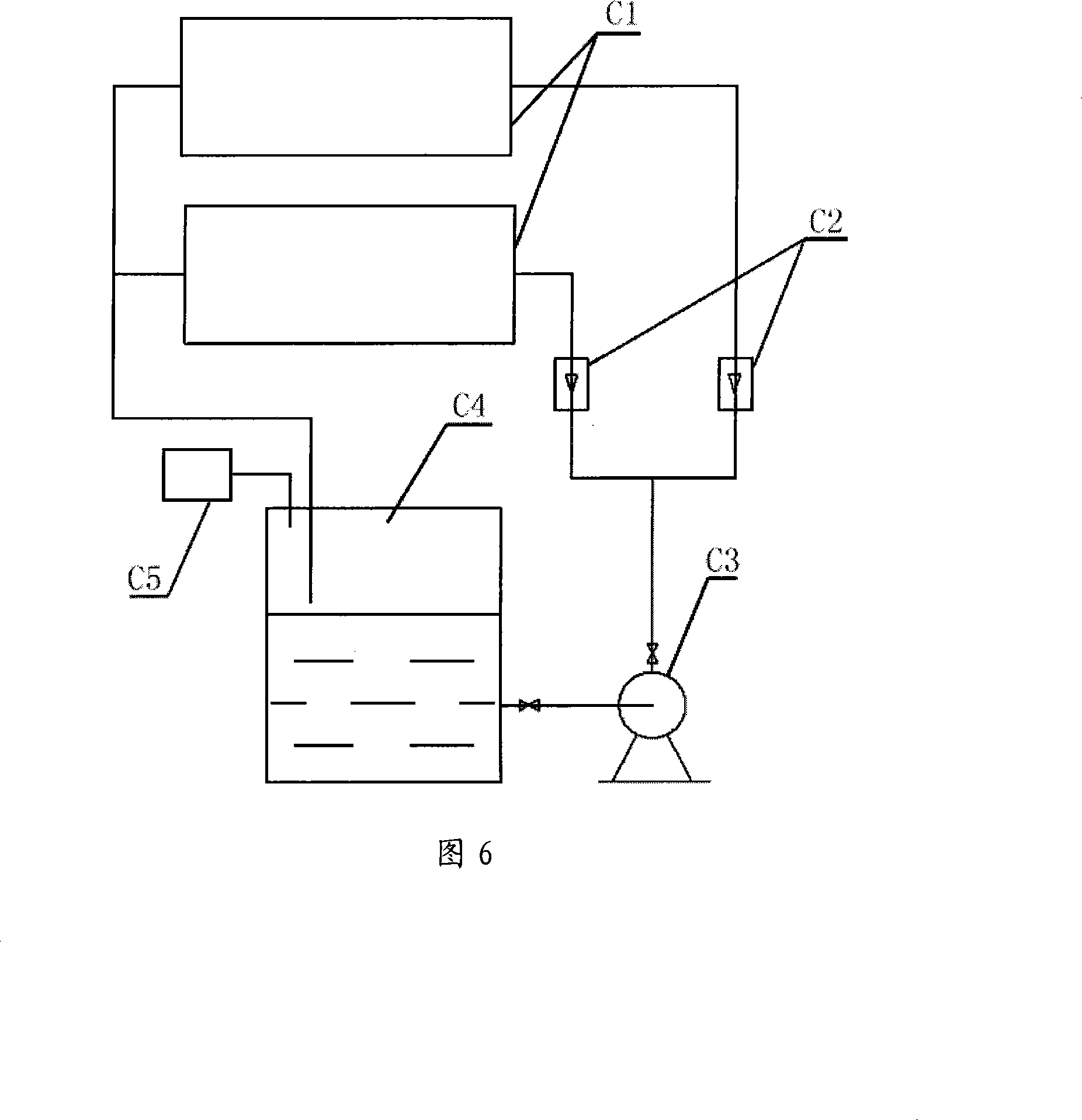
[0039] As shown in FIG. 6 , an embodiment of the present invention further provides an electrolysis system based on the electrolytic cell described in Embodiment 1, the system comprising:

[0040] Using the electrolytic cell C1 described in the first embodiment, the liquid inlet of the liquid inlet end plate of the electrolytic cell C1 is connected to the circulating tank C4 through the pipeline, the flow meter C2, and the circulating pump C3. The solution;

[0041] The liquid outlet of the liquid outlet end plate of the electrolytic cell C1 is directly connected to the circulation tank C4 through a pipeline;

[0042] The circulation tank C4 is provided with a gas absorption device C5, and the gas absorption device C5 processes the gas generated when the electrolysis tank C1 is operated and flows back to the circulation tank C4 through the pipeline.

[0043] In order to ensure the flow rate of the electrolyte, the electrolyte is pressed in from the liquid inlet end plate by t...


PUM

PropertyMeasurementUnit
sizeaaaaaaaaaa
thicknessaaaaaaaaaa
thicknessaaaaaaaaaa

Abstract

The invention discloses a sealed electrolysis bath and an electrolytic system, the electrolysis bath comprises two end plates, an anode component, a cathode component, sealing components and a compacting device, wherein liquid flowing ports are evenly arranged on the two end plates, liquid flowing through-holes are correspondingly arranged on the anode component and the cathode component, the anode component and the cathode component are separately arranged between the two end plates, a polar chamber is formed between the anode component and the cathode component, the sealing components are evenly arranged on the contact position of the anode component, the cathode component and the end plates, and the anode component, the cathode component and the end plates form a sealed structure after being compacted through the compacting device. The electrolysis bath has simple structure and can increase the circulation speed of electrolyte, the overpotential is effectively lowered, the current density of an anode and a cathode is increased when in electrolysis, the productivity of unit electrolysis bath is increased, and the electrolysis bath can be widely applied in electrowinning various metal and in electrowinning metallic solution with low concentration. The sealed structure avoids the influence of gas which is discharged in the electrolysis process to environment in a workshop.

Description

technical field [0001] The invention relates to an electrolytic cell technology, in particular to a closed electrolytic cell and an electrolytic system suitable for metal electrowinning. Background technique [0002] In the existing production technology, the general electrolytic cell is an open electrolytic cell. Due to the slow flow rate of the electrolyte, it is difficult for the liquid to ensure a uniform flow rate, and uneven flow and dead ends are prone to occur, which not only makes the current distribution on the electrodes uneven. , resulting in a decrease in the electrolytic current density, and due to the slow flow rate, the laminar flow layer on the electrode surface is wider, so that the concentration of the electrolyte on the electrode plate surface becomes lower, resulting in concentration polarization, the cell voltage rises, and the secondary The opportunity for the reaction to occur, thus limiting the increase of the current density during electrolysis; in ...

Claims


Application Information

Patent Timeline
Patent Type & Authority Applications(China)
IPC IPC(8): C25C7/00
Inventor 王振文江培海尹飞
Owner BEIJING GENERAL RES INST OF MINING & METALLURGY
Why Eureka
Try Eureka