Device for detecting and removing foreign matter

A technology for separating out and impurity, which is applied in the field of impurity devices, can solve the problems of adverse effects on optical efficiency and loss, and achieve the effect of high impurity removal rate and high optical efficiency

Inactive Publication Date: 2008-08-27
USTER TECHNOLOGIES
View PDF0 Cites 2 Cited by
  • Summary
  • Abstract
  • Description
  • Claims
  • Application Information

AI Technical Summary

Problems solved by technology

Due to the use of semi-transparent mirrors for light couplin

Method used


Image

  • Device for detecting and removing foreign matter
  • Device for detecting and removing foreign matter
  • Device for detecting and removing foreign matter

Examples


Embodiment Construction

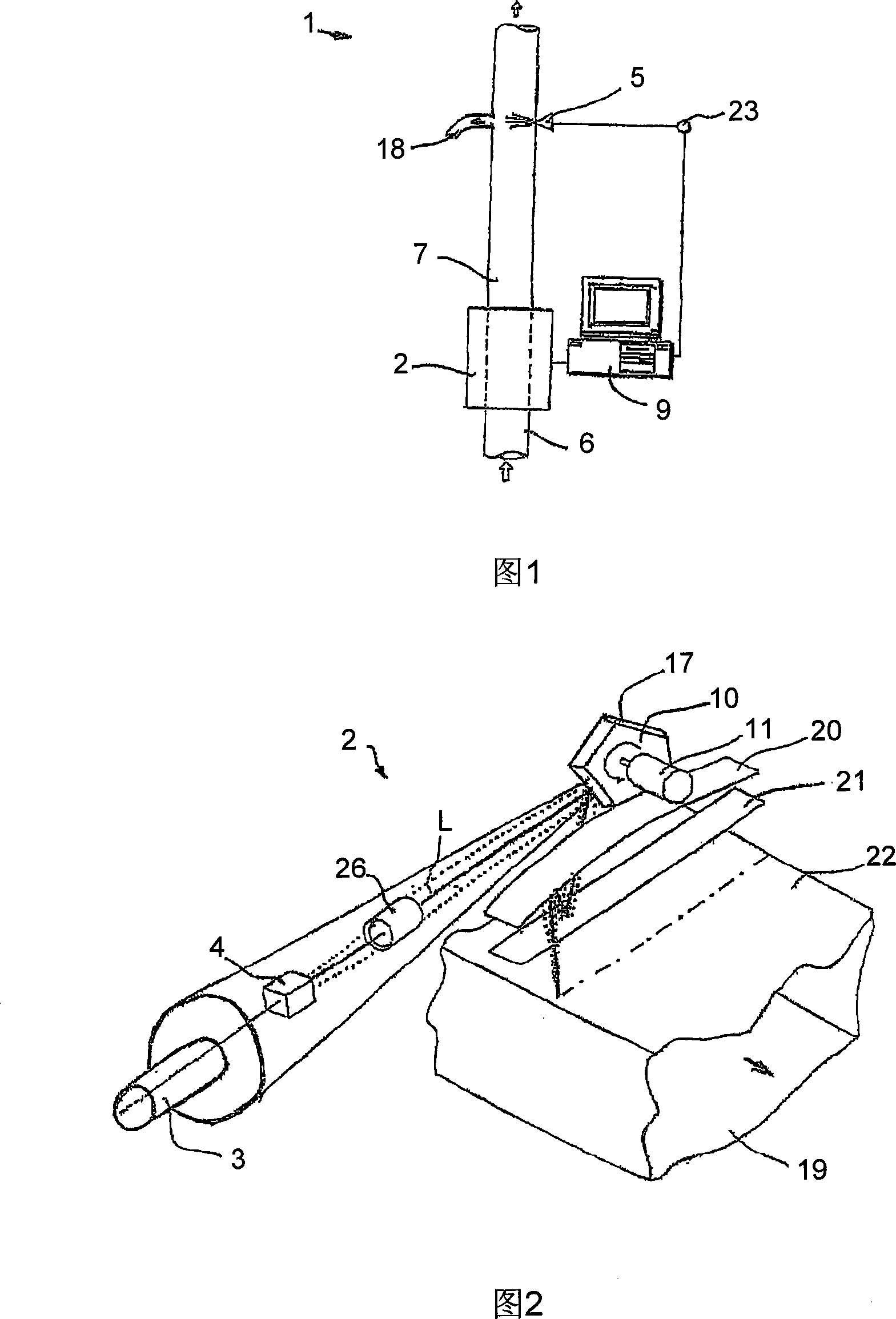
[0042] FIG. 1 shows a device, designated 1 , for detecting and separating impurities in a pneumatically conveyed stream of raw cotton material. The basic structure known per se essentially comprises a detection unit 2 for detecting impurities in a material flow, and a separation device 5 operatively connected to the detection unit. The material flow is conveyed via a conveying line 6 , where a corresponding observation channel 7 is provided in the region of the detection unit 2 .

[0043] When impurities are detected, the corresponding fact is converted by the evaluation unit 9 into a control signal for activating the separating device 5 . The detected impurities are now sent away through the separation pipe 18 or other discharge line until they finally reach a waste container (not shown). In FIG. 1, the separation is accomplished, for example, with compressed air (indicated by compressed air source 23) or directly by blowing out impurities or by operating deflecting shutters...


PUM


Abstract

The invention provides a device for detecting and separating impurities in a material flow, including a radiation mechanism (3) for radiating the material flow and at least one a sensor device (4) for detecting the radiated impurities in the material flow. A rotatable polygonal mirror (10) for scanning the material flow row by row is provided, radiation of the radiation mechanism (3) can be deflected to the material flow and the radiation reflected by the material flow can be deflected to the sensor device (4) both by utilizing the polygonal mirror. The radiation mechanism (3) and the sensor device (4) are arranged coaxially with one being in front and the other being back with regard to an optical irradiation shaft (L). The radiation mechanism (3) mainly comprises a radiation source (8), a concave reflecting mirror (11) for collimate the radiation to the polygonal mirror (10) along the optical irradiation shaft (L), and a back reflector (12), by which back side of the radiation can be guided toward the concave reflecting mirror (11).

Description

technical field [0001] The invention relates to a device for detecting and separating out impurities in a material flow. Such devices are mainly used in spinning mills for raw cotton cleaning. Raw cotton often contains impurities which are undesirable in the spinning process. Impurities may be, for example, cordage, jute or other fabric scraps, plastic film or material particles. Background technique [0002] A device of a similar type is disclosed eg in Jörg Ullmann's paper "Detection of Impurities in Raw Cotton" (Zurich 1996, see Chapter 5.1 with reference to Figure 5.1). Here, the lint travels through the display channel in a pneumatic conveying stream and is monitored with the aid of a flying spot scanner. To scan the material flow in rows, a prism-shaped mirror wheel is provided, to which a light source arrangement with a laser and a sensor arrangement are aligned, where the laser beam is directed towards the mirror wheel by optical coupling. In addition, the light ...

Claims


Application Information

Patent Timeline
IPC IPC(8): D01G9/00D01G5/00G01N21/89
CPCD01G31/003
Inventor A·克劳斯
Owner USTER TECHNOLOGIES
Why Eureka
Try Eureka