Piston molded line cam lift synthetic checking instrument

A cam lift, inspection instrument technology, applied in instruments, measuring devices, optical devices, etc., can solve the problems of large equipment investment, difficult maintenance, poor versatility, etc., to eliminate coaxiality errors, improve detection efficiency, and manufacture. low cost effect

Inactive Publication Date: 2008-08-27
安徽华祥实业有限公司
View PDF0 Cites 17 Cited by
  • Summary
  • Abstract
  • Description
  • Claims
  • Application Information

AI Technical Summary

Problems solved by technology

[0002] For the detection of the convex ellipse of the outer contour of the aluminum piston skirt of an internal combustion engine and the phase angle of the camshaft cam lift during the manufacturing process, most industry manufacturers use piston ellipse testers, optical dividing heads and Abbe length measuring instruments for detection. During the production testing process, these testing instruments have the disadvantages of low efficiency and large equipment investment, which are not suitable for the company's production needs. It takes 4 to 6 hours to detect the included angle of the plane once, and it takes 4 to 6 hours to locate and read the indicated value
The disadvantage of using the piston profile detector is that it can only detect the profile of the piston, but not the cam lift, and the versatility is poor.
At the same time, it is difficult to maintain, and it often occurs that the equipment is damaged and cannot be repaired in time, which affects production

Method used


Image

  • Piston molded line cam lift synthetic checking instrument
  • Piston molded line cam lift synthetic checking instrument
  • Piston molded line cam lift synthetic checking instrument

Examples


Embodiment Construction

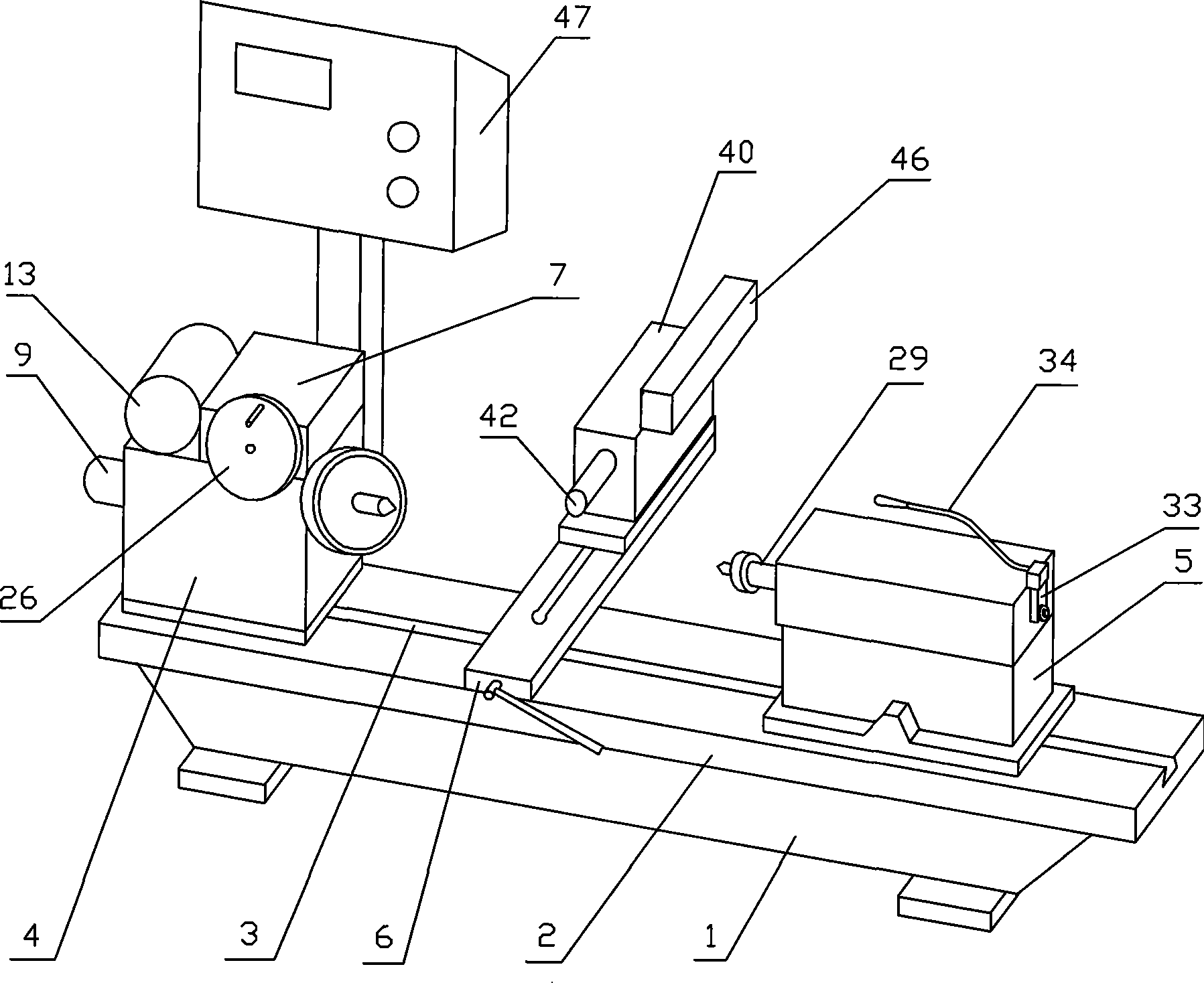
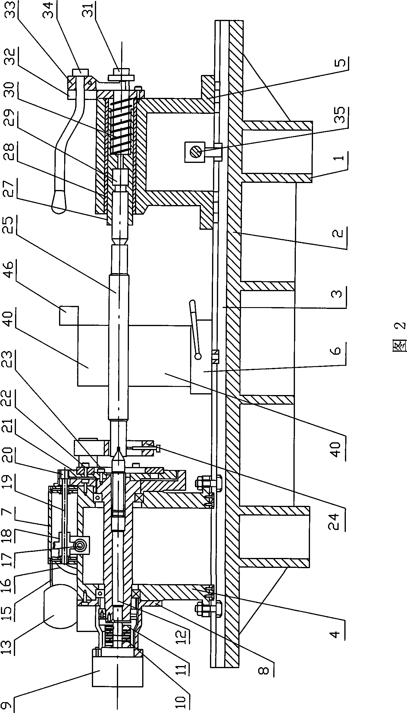
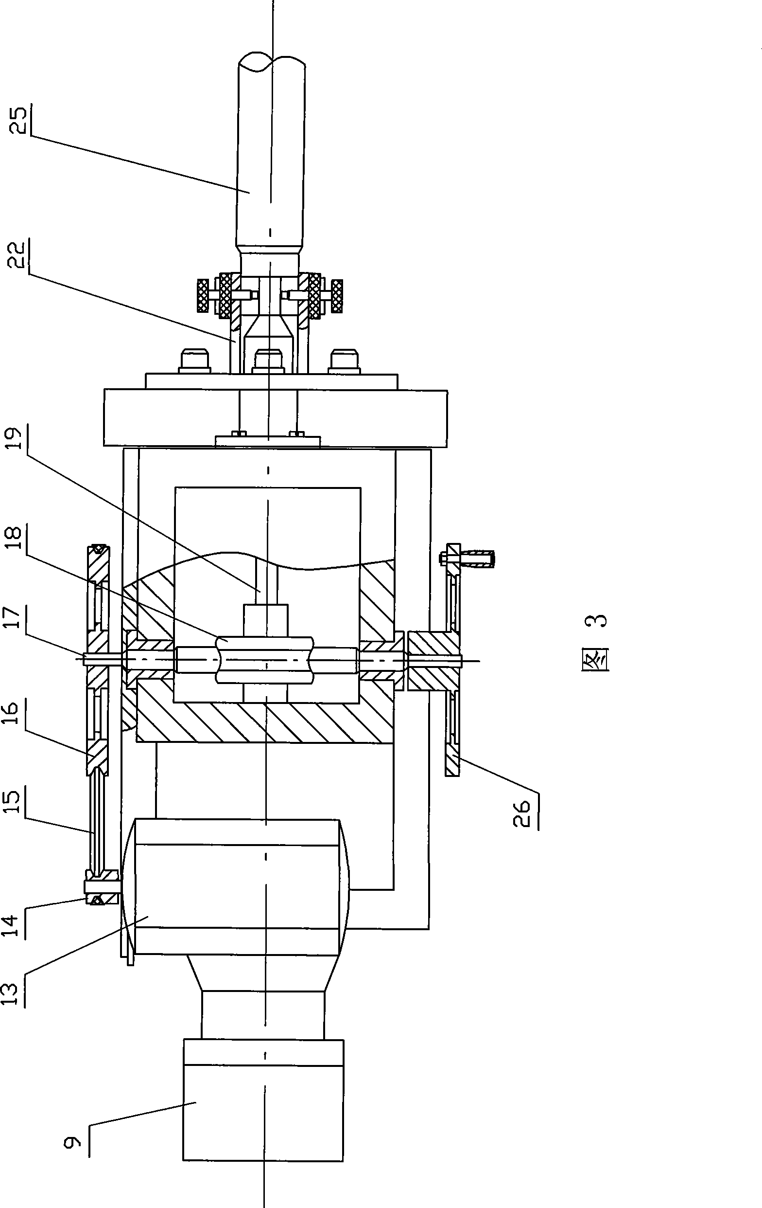
[0011] Depend on figure 1 , Fig. 2, Fig. 3 can be seen, the piston profile cam lift comprehensive inspection instrument of the present invention comprises the bed 1 and the guide rail platform 2 on the bed, the guide rail platform 2 is provided with T-shaped groove 3, is connected laterally on the T-shaped groove 3 Main shaft seat 4 and tail stock 5 are arranged, length measuring instrument base plate 6 is arranged longitudinally, and main shaft seat 4 is fixedly connected with T-shaped slot 3 with bolts and nuts. The main shaft seat 4 is equipped with a transmission seat 7, and the left end is connected to the encoder interface seat 8. The circular grating rotary encoder 9 is mounted on the encoder interface seat 8 and connected with bolts. There is an elastic sheet 10 in the middle of the circular grating rotary encoder 9. The shaft device 11 bears torque, and the shaft coupling 11 is connected with the main shaft 12 , and the main shaft 12 passes through the bearings at bot...


PUM


Abstract

The invention discloses a comprehensive inspection instrument for a piston profile cam lift range. A guide rail platform of a machine body is horizontally connected with a spindle drum and a tailstock, and is longitudinally connected with a bottom plate of a length measuring instrument, the left end of a driver seat on the spindle drum is provided with a round grating rotary encoder the middle of which is provided with an elastic slice winding a coupling to bear the torque force; a motor is connected with a worm and worm wheel mechanism, a pinion on a worm-wheel shaft is meshed with a gear outside the right side of the spindle drum, the gear is connected with an eccentric chuck, a catch plate and a lathe dog; a sliding shaft is arranged in a transition sleeve at the middle of the tailstock, a finial spindle is connected with a screw through a spring, the right side of the tailstock is provided with a shift fork device; the middle of a grating fixing base is provided with an adjusting screw, a compression spring and a measuring rod are arranged in the rear cavity of the adjusting screw, the grating fixing base is provided with a length grating ruler and a grating sensor; the round grating rotary encoder and the grating sensor are connected with a digital display control device. The comprehensive inspection instrument solves the problems that the prior art is not universal, time consuming and difficult in maintenance, and has the characteristics of high detection efficiency and measurement accuracy, long service life and low cost.

Description

1. Technical field [0001] The invention relates to a testing device for auto parts, in particular to a comprehensive testing instrument for piston profiles and cam lifts. 2. Background technology [0002] For the detection of the convex ellipse of the outer contour of the aluminum piston skirt of an internal combustion engine and the phase angle of the camshaft cam lift during the manufacturing process, most industry manufacturers use piston ellipse testers, optical dividing heads and Abbe length measuring instruments for detection. During the production testing process, these testing instruments have the disadvantages of low efficiency and large equipment investment, which are not suitable for the company's production needs. It takes 4 to 6 hours for the positioning and reading of the indication value to detect the included angle of the plane once. The disadvantage of using the piston profile detector is that it can only detect the profile of the piston, but not the cam li...

Claims


Application Information

Patent Timeline
Patent Type & Authority Applications(China)
IPC IPC(8): G01B11/00
Inventor 李善明杨煜
Owner 安徽华祥实业有限公司
Why Eureka
Try Eureka