EHD intensification minitype heat radiating device

A heat sink and micro technology, applied in indirect heat exchangers, lighting and heating equipment, cooling/ventilation/heating renovation, etc., can solve the problems of high cost and complex system, reduce flow resistance and increase capillary driving force , Improve the effect of capillary driving force

Inactive Publication Date: 2008-08-27
BEIJING UNIV OF TECH
View PDF2 Cites 13 Cited by
  • Summary
  • Abstract
  • Description
  • Claims
  • Application Information

AI Technical Summary

Problems solved by technology

However, the technology is expensive and complex

Method used


Image

  • EHD intensification minitype heat radiating device
  • EHD intensification minitype heat radiating device
  • EHD intensification minitype heat radiating device

Examples


Embodiment Construction

[0023] Attached below Figure 1~5 The present invention is further described.

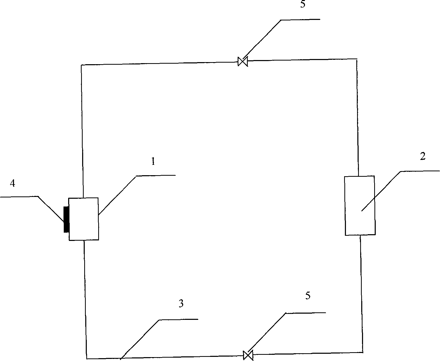
[0024] Such as figure 1 As shown, this embodiment includes an evaporator 1, a condenser 2, a soft plastic capillary 3, a high voltage generating device and electrodes. The components in this embodiment are composed of soft plastic capillary tubes 3 in series in the order of condenser 2 and capillary evaporator 1 (with high-voltage electrodes 9 inside) to form a one-way circulation loop.

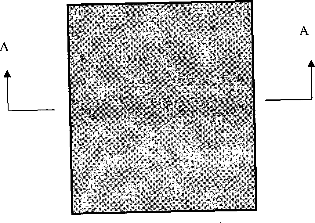
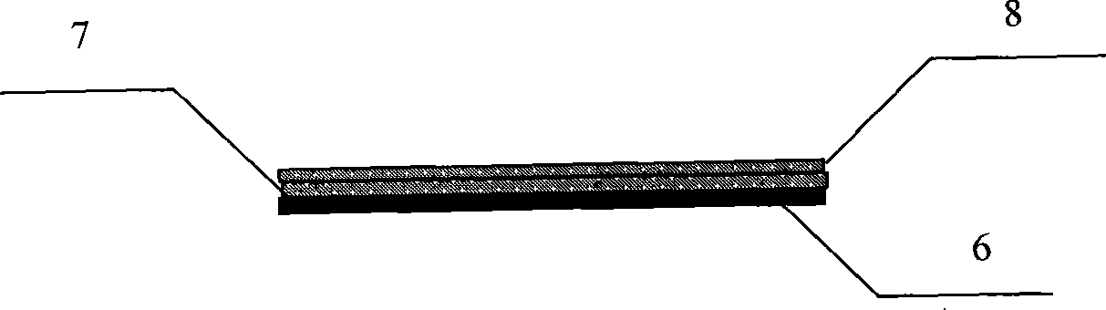
[0025] The layout of the capillary wick evaporator is shown in Figure 2. The capillary wick in the evaporator 1 is a combined capillary core fixed on the substrate 6, and the combined capillary core includes an inner layer of wire mesh and an outer layer of wire mesh, as shown in Figure 2(b ) shown. The pore size of the inner screen 7 is greater than 15 μm, and the pore size of the outer screen 8 is in the range of 5 μm˜10 μm. In this way, when the evaporator is working, the pore diameter of the inner capillar...


PUM


Abstract

The invention relates to a heat sink cooling device of an electronic device, in particular to miniature heat sink intensified through the EHD and used for the electronic device under the condition of high heat-flow density. The miniature heat sink comprises an evaporator, a condenser (2), a soft plastic capillary pipe (3), and high voltage electrodes (9) which are distributed at the both sides of the capillary in the evaporator and are parallel with the evaporating surface of the evaporator. The evaporator, the soft plastic capillary pipe (3) and the condenser (2) are connected in series to form a one-way circulating loop. The capillary core of the evaporator adopts a combined capillary core fixed on a base plate (6), and comprises inner and outer layers, the aperture of the inner layer capillary core is layer, and the aperture of the outer layer capillary core is smaller. The high voltage electrodes can intensify the vaporization and the heat transfer of the evaporator. Through adopting the heat sink, real-time sufficient cooling can be performed to the electronic device with high heat-flow density, therefore, the requirements of heat emission of the computer chips with high performance, the high energy laser and the other electronic devices.

Description

technical field [0001] The invention relates to a heat radiation cooling device of an electronic device, in particular to an EHD-strengthened miniature heat dissipation device used in the high heat flux density condition of the electronic device. Background technique [0002] With the high frequency and high speed of electronic devices, the rapid development of integrated circuit technology and the advancement of MEMS (MicroElectronic Mechanical System) technology, the heat generation and heat flux density of electronic devices per unit volume have increased significantly, and the layout and design of heat dissipation devices have encountered difficulties. more and more constraints. Taking the design of microelectronic chips as an example, it has generally reached (60-100) W / cm 2 , up to 200W / cm 2 above. Traditional heat dissipation methods such as air cooling (forced convection) are commonly used, because the cooling efficiency is proportional to the speed of the fan. W...

Claims


Application Information

Patent Timeline
Patent Type & Authority Applications(China)
IPC IPC(8): H05K7/20H01L23/427F28D15/02
CPCH01L2924/0002
Inventor 刁彦华赵耀华王樱于雯静
Owner BEIJING UNIV OF TECH
Why Eureka
Try Eureka