
Pipe gas phase biological filtering device

A technology of biological filtration and biological filter, which is used in air quality improvement, dispersed particle separation, chemical instruments and methods, etc., can solve the problems of large bed height, large packing layer height, low volume load, etc., and achieves a simple and compact structure. , Small filler thickness, small footprint effect

Inactive Publication Date: 2008-09-17
HUNAN UNIV
View PDF0 Cites 10 Cited by
  • Summary
  • Abstract
  • Description
  • Claims
  • Application Information

AI Technical Summary

Problems solved by technology

Although bio-trickling filter devices using synthetic fillers have a smaller volume, they have problems such as excessive packing layer height, long gas residence time, low volume loading rate, unstable long-term operation performance, and easy blockage of the filter bed.
[0005] To sum up, the existing widely used gas-phase biological filtration system has a bed or tower structure and a top-down or bottom-up airflow mode in the packing, which has problems such as excessive bed height, low volume load, and treatment problems. The shortcomings of relatively small volume, uneven gas distribution, and large pressure drop severely limit the industrial practical application of gas-phase biological filtration technology.

Method used


Image

  • Pipe gas phase biological filtering device
  • Pipe gas phase biological filtering device

Examples


Embodiment Construction

[0035] The present invention will be described in further detail below in conjunction with the accompanying drawings and specific embodiments.

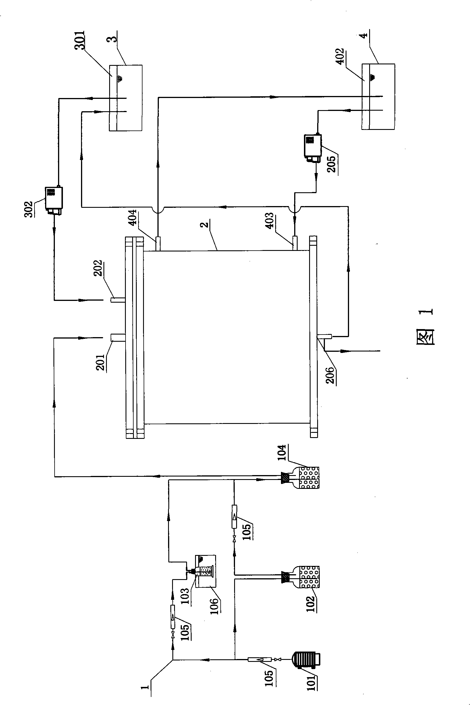
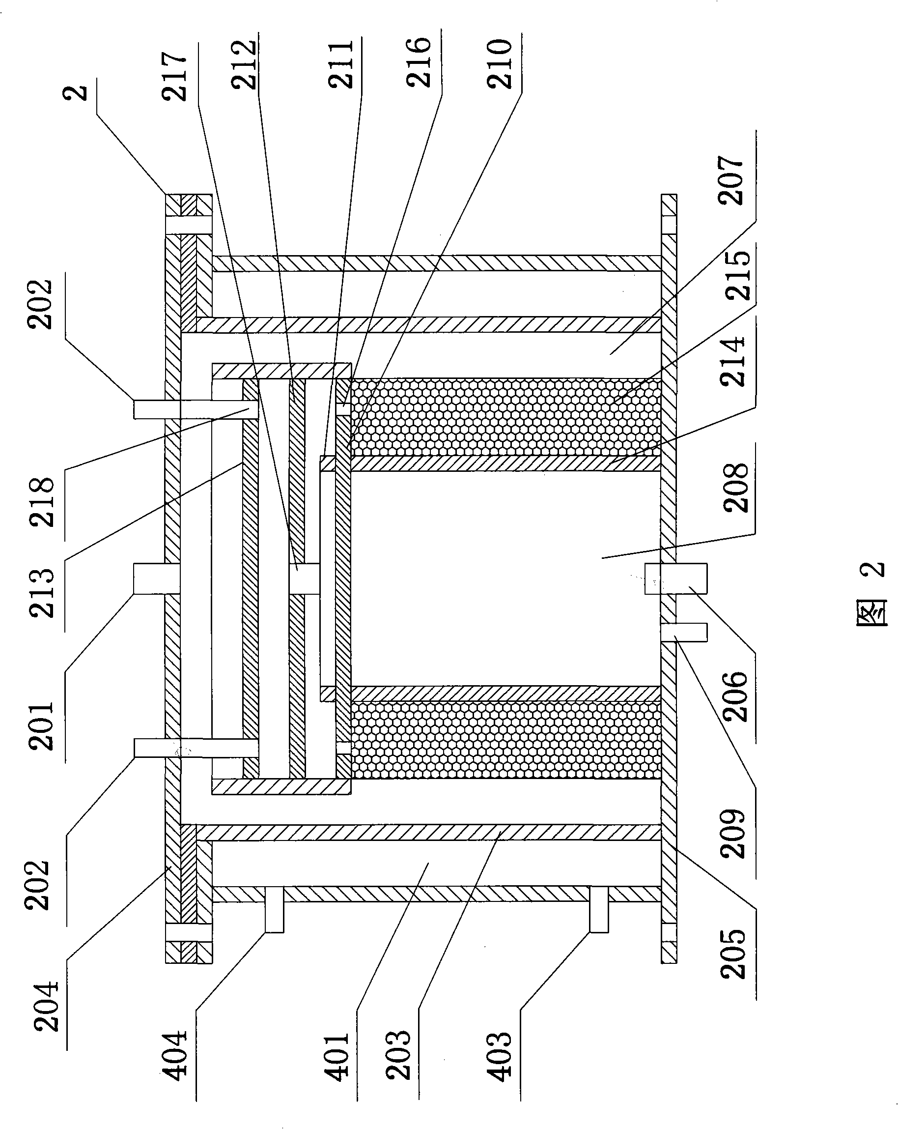
[0036]As shown in Fig. 1 and Fig. 2, a kind of tubular gas-phase biological filtration device of the present invention, it comprises waste gas supply device 1, biofilter 2 and nutrient solution supply device 3, and biofilter 2 comprises cylindrical housing 203, top The cover plate 204, the base plate 205 and the tubular packing device installed in the inner cavity of the cylindrical shell 203, the top cover plate 204 is provided with an air inlet 201 and the nutrient solution inlet 202, and the base plate 205 is provided with a waste liquid discharge port 206 and Exhaust port 209, an annular gas channel 207 is formed between the tubular packing device and the inner wall of the cylindrical shell 203, and the central cavity of the tubular packing device forms an air chamber 208 in the pipe. One end of the air chamber 208 in the pipe comm...


PUM

PropertyMeasurementUnit
Apertureaaaaaaaaaa
Bulk densityaaaaaaaaaa

Abstract

The invention relates to a tubular gaseous biological filtering device, comprising a waste gas feeding device, a biofilter and a nutrient solution feeding device, wherein, the biofilter comprises a cylindrical casing, a top cover plate, a bottom plate and a tubular filling device arranged in the inner cavity of the cylindrical casing, an air inlet and a nutrient solution inlet are arranged on the top cover plate, a waste liquid discharge outlet and an exhaust outlet are arranged on the bottom plate, a ring shape gas passage is formed between the tubular filling device and the internal wall of the cylindrical casing, the central hollow cavity of the tubular filling device can form a tube gas chamber, one end of the tube gas chamber is communicated with the air inlet and the other end is communicated with the outside world through the exhaust outlet, the circular filler layer of the tubular filling device is communicated with the inlet of nutrient solution, the waste gas feeding device and the nutrient solution feeding device are separately connected with the air inlet of the biofilter and the inlet of the nutrient solution. The tubular gaseous biological filtering device has the advantages of simple and compact structure, tubular porous filling structure and inward or outward airflow mode for filling with small filling thickness, large volume loading and high handling capacity.

Description

technical field [0001] The invention mainly relates to the technical field of biological filtration for air pollution control, in particular to a tubular gas phase biological filtration device. Background technique [0002] Gas-phase biological filtration technology refers to the 2 S, NH 3 When the exhaust gas of inorganic substances or volatile organic substances passes through the gas-phase biofiltration reactor, the gaseous pollutants are transferred from the gas phase to the interior of the biofilm attached to the filter medium, and are decomposed and converted into biofilm through the metabolism of microorganisms (enzymes). Substance and CO 2 、H 2 O and other inorganic substances. Therefore, it has the advantages of being environmentally friendly, cost-effective, easy to operate, and suitable for treating low-concentration air volume waste gas, and has been increasingly paid attention to by people. [0003] At present, the widely used biological filtration devices ...

Claims


Application Information

Patent Timeline
IPC IPC(8): B01D53/85
CPCY02A50/20
Inventor 杨春平陈宏曾光明谢更新钟袁元余关龙雷敏王家强
Owner HUNAN UNIV
Learn More