
System and method for dual-channel optical phase modulation mm wave generation and remote vibration provision in mm wave optical transmission system

An optical fiber transmission and phase modulation technology, applied in electromagnetic wave transmission system, transmission system, free space transmission and other directions, can solve the problems of complex millimeter wave generation technology system, high cost and difficult maintenance.

Inactive Publication Date: 2008-09-17
SHANGHAI UNIV
View PDF0 Cites 21 Cited by
  • Summary
  • Abstract
  • Description
  • Claims
  • Application Information

AI Technical Summary

Problems solved by technology

[0009] The purpose of the present invention is to solve the problems of complex system, high cost and difficult maintenance in the existing millimeter wave generation technology, and propose a system and method

Method used


Image

  • System and method for dual-channel optical phase modulation mm wave generation and remote vibration provision in mm wave optical transmission system
  • System and method for dual-channel optical phase modulation mm wave generation and remote vibration provision in mm wave optical transmission system
  • System and method for dual-channel optical phase modulation mm wave generation and remote vibration provision in mm wave optical transmission system

Examples


Embodiment Construction

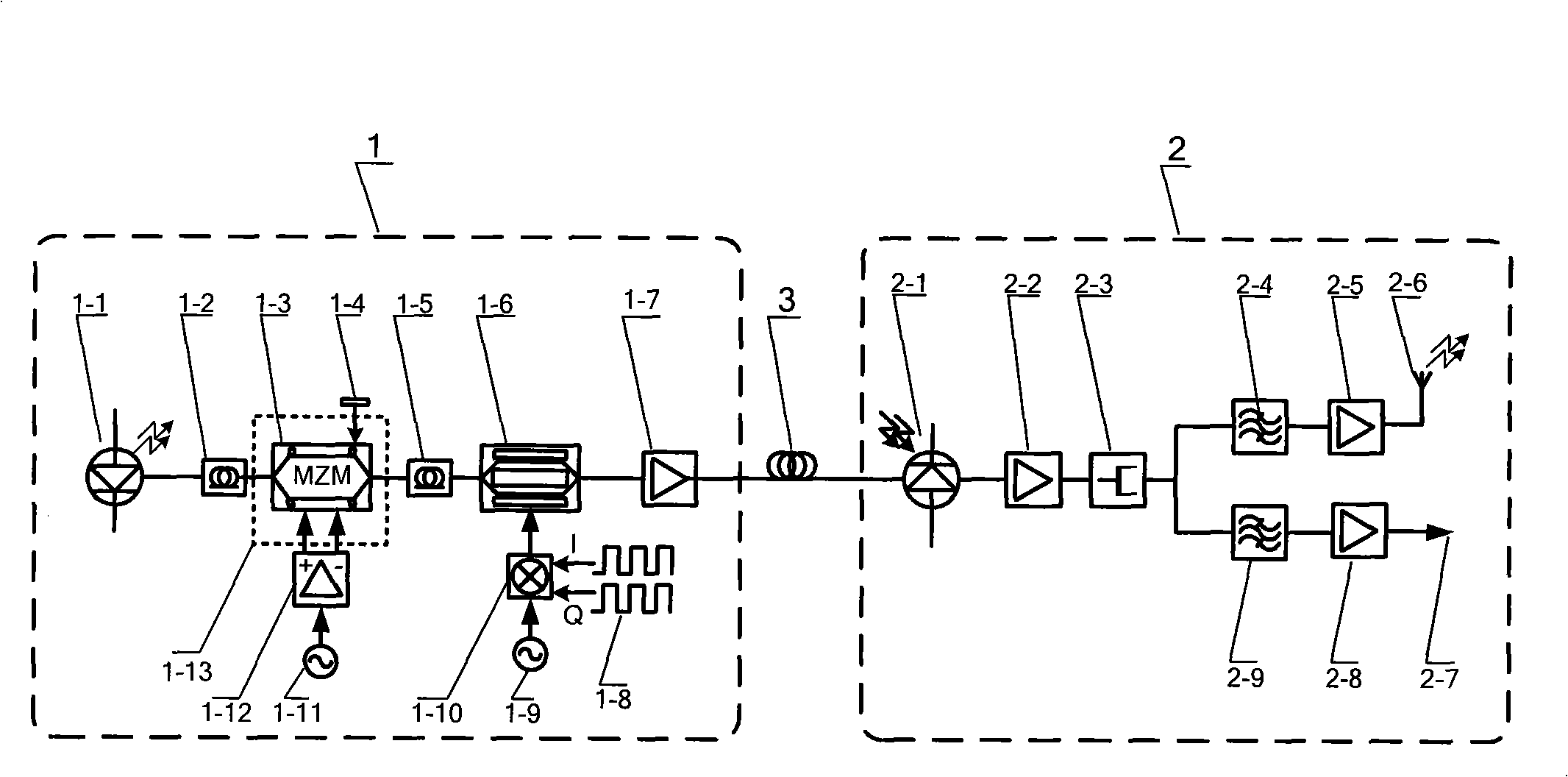
[0049] A preferred implementation example of the present invention is a downlink transmission system and method applied to a 38GHz RoF system: see figure 1 , the system for generating the two-way optical phase modulation millimeter wave and providing the remote local oscillator in the millimeter wave optical fiber transmission system includes a central station 1, a base station 2 and an optical fiber 3 connecting them. The structure of the central station 1 is as follows: a laser 1-1 is connected with a polarization controller 1-2 through a pigtail, and the polarization controller 1-2 is connected with a two-electrode Mach-Zehnder modulator 1-3 through a pigtail The optical input terminal is connected; a cosine microwave signal source 1-11 is connected to the input terminal of a microwave differential power amplifier 1-12, and the two output terminals of the microwave differential power amplifier 1-12 are respectively connected to the two-electrode Mach -The two RF input termi...


PUM


Abstract

The present invention relates to a system for generating a two-way light phase modulation millimeter wave and providing remote local oscillator in a millimeter wave optical fiber transmission system and a method thereof. The system comprises a center station and a base station. The center station is composed of a laser, two polarization controllers, a double-electrode Mach-Zehnder modulator, a microwave difference power amplifier, a light intensity modulator, an optical fiber amplifier and the like. The base station is composed of a photodetector, a front low-noise amplifier, a power divider,two band-pass filters, two millimeter wave amplifier and a millimeter wave transmitting antennae. In the method, a single mode laser is divided into two routes at the center station. Two opposite-phase 5GHz cosine microwave signals are used for phase modulating with large modulation index to the two routes of optical wave. The two routes of optical waves are overlapped. The phase variation of theoptical wave is switched to a strength variation through a FM-IM effect. The strength variation comprises a microwave signal and a high order component thereof. The millimeter wave signal is obtainedby extracting the high order harmonic. Then the optical fiber is executed with a strength modulation with a 2GHz BPSK signal and a mode of regulated subcarrier through a light intensity modulator. A 40GHz millimeter wave remote reference local oscillator and a 38GHz BPSK signal are obtained at the base station. The number of optical frequency doubling gets to 8, and the speed of baseband data transmission gets to 200Mbps.

Description

Technical field: [0001] The invention relates to a system and a method for generating and providing a remote local oscillator in a millimeter wave optical phase modulation millimeter wave in a millimeter wave optical fiber transmission (RoF) system. Its core idea is to divide the single-mode laser into two paths at the central station, and perform phase modulation on the two paths of light waves with a large modulation index by two anti-phase 5GHz cosine microwave signals, and then superimpose the two light waves, thus generating FM- The IM effect converts the phase change of light waves into intensity changes. The intensity changes include microwave signals and their high-order harmonic components, and the high-order harmonics are extracted to obtain millimeter-wave carriers. Then use the 2GHz BPSK signal to modulate the intensity of the light wave in the form of a modulated subcarrier, and the 40GHz millimeter wave remote reference local oscillator and the 38GHz BPSK signal ...

Claims


Application Information

Patent Timeline
IPC IPC(8): H04B10/155H04B10/17H04B10/10H04B10/11
Inventor 朱美伟林如俭叶家骏周喆赟
Owner SHANGHAI UNIV
Learn More