Laser impact tiny bulk forming method and apparatus for tiny apparatus

A technology of laser shock and micro devices, which is applied in laser welding equipment, welding equipment, metal processing equipment, etc.

Inactive Publication Date: 2008-09-24
JIANGSU UNIV
View PDF16 Cites 48 Cited by
  • Summary
  • Abstract
  • Description
  • Claims
  • Application Information

AI Technical Summary

Problems solved by technology

There have been many patent technology reports on laser shock-based forming and material modification at home and abroad, such as Chinese patents 01134063.0, 200510094159.5, 02138336.7, 200610039505.4, 200610096475.0, US patents US334612, US3850698, US4401477, US6554921, US406 A-58120716, JP 2006-320907, etc., but they all focus on how to use laser

Method used


Image

  • Laser impact tiny bulk forming method and apparatus for tiny apparatus
  • Laser impact tiny bulk forming method and apparatus for tiny apparatus
  • Laser impact tiny bulk forming method and apparatus for tiny apparatus

Examples


specific Embodiment approach 1

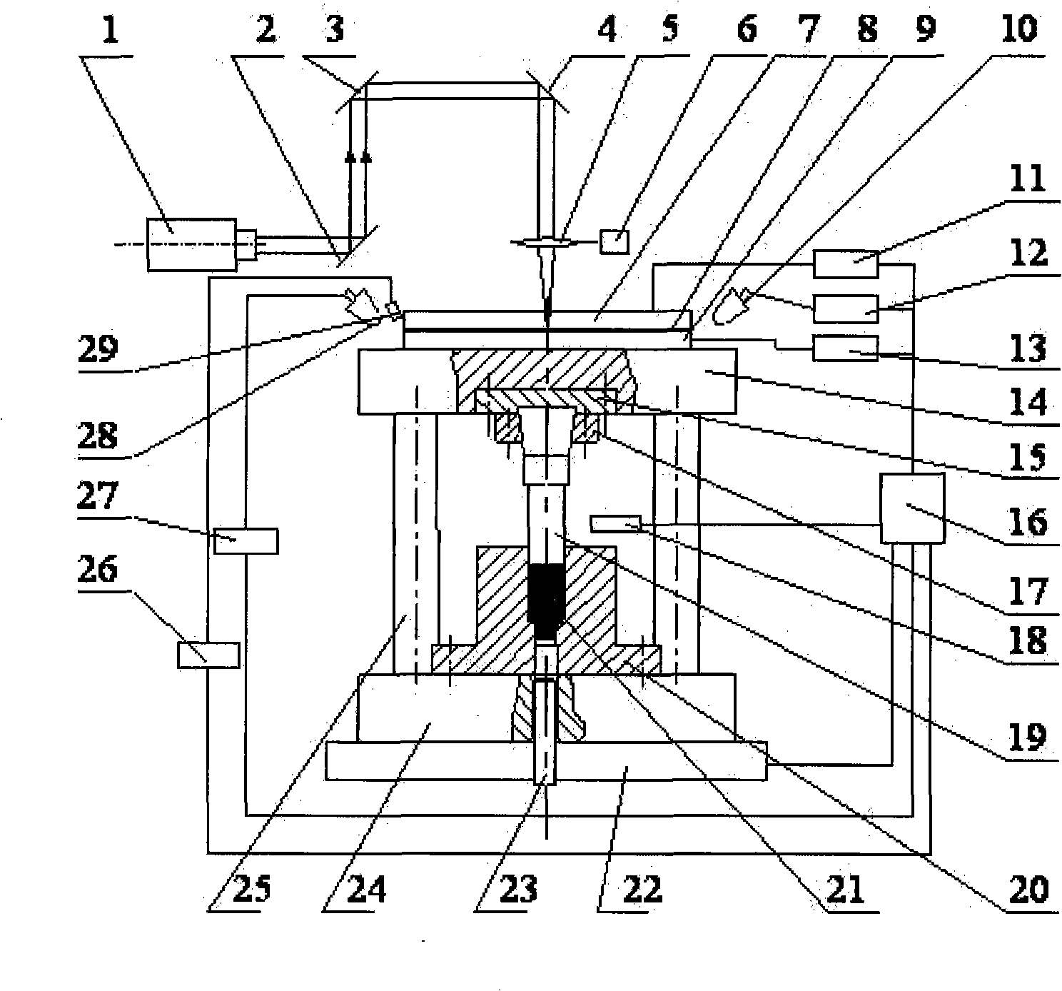
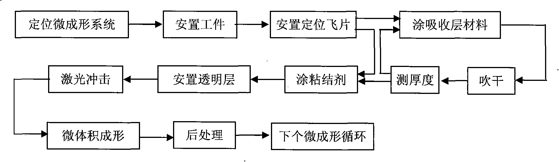
[0043] combine figure 1 , figure 2 with Figure 4 , the laser shock micro volume forming method of micro devices is as follows:

[0044] Design and process the punch 19 and the die 20 according to the shape, size and precision of the micro-devices that need to be micro-formed. In the mold base 14, the die 20 is arranged on the lower mold base 24, and the lower mold base 24 is placed on the workbench 22, and the guide mechanism is connected with the upper mold base 14 and the lower mold base 24 respectively; X, Y and Z direction movement, adjust the relative position of the punch 19 and the die 20 in the microplastic forming system and the centering situation of the punch 19 and the die 20, if the punch 19 and the die 20 pass through a period of time After forming, due to the wear of the mold, it needs to be re-centered and positioned. At this time, it can be re-located and centered by controlling the movement of the worktable 22 or adjusting the height of the backing plate...

specific Embodiment approach 2

[0045] combine figure 1 , figure 2 , Figure 4 , Figure 5 with Image 6 , the laser shock micro volume forming method of micro devices is as follows:

[0046] According to the shape, size and precision of the micro-devices that need to be micro-formed, a punch 34 and a die 36 with a periodically repeating array structure are designed and processed. A punch array 37 with a repeating structure is distributed on the punch 34. On the die 36 The concave mold cavity array 35 in the form of repeated structure is distributed, and the micro-forming system is installed according to the first embodiment; the computer 16 is used to control the movement of the worktable 22 in the X, Y and Z directions, and the convex mold 34 and the concave mold 36 in the microplastic forming system are adjusted. The relative position of the punch 34 and the centering of the die 36, if the punch 34 and the die 36 need to be re-centered and positioned due to the wear of the mold after a period of form...


PUM


Abstract

The invention provides a laser impulse micro-bulk forming method and a device thereof, being suitable for the micro-bulk forming of a planchet and belonging to the laser micro-processing field and micro-bulk forming field. The forming method is as follows: impulse wave induced by laser is used as a forming force source for micro-device micro-bulk forming; laser burst generated by a laser generator according to requirements is irradiated at a flying-piece surface layer passing through a transparent restraint layer through an external light path system; a high temperature and high pressure plasma body is generated and the impulse wave is formed; overhigh pressure of the impulse wave is used for driving the flying-piece and a micro-plastic forming system connected with a flying piece; a micro-workpiece is pressed; the micro-bulk forming of the workpiece is finished. The device applied to the method comprises six parts of the laser generator, an external light path system, an induction impulse wave generation system, a micro-plastic forming system, a control system and an operating platform. The laser impulse micro-bulk forming method can be used for realizing the micro-bulk forming of any complex shaped micro-devices, and can be repeatedly impacted and loaded on, and has good repeatability and easy realization of automatic production.

Description

technical field [0001] The present invention relates to the fields of laser micromachining and microvolume forming, in particular to a method and device for laser shock microvolume forming of micro devices, which can accurately copy micro features on micro molds to micro workpieces, and is suitable for micro devices of micro devices. Volume precision forming is especially suitable for the micro-volume forming of complex devices that are difficult or impossible to form by conventional methods at the micro-scale, and is suitable for low-cost mass production of micro-devices. Background of the invention [0002] Miniaturization is an important way to obtain competitive and multi-functional engineering systems. With the development of modern science and technology and the increasing demand for micro-parts and micro-devices, miniaturization has become an important direction for the development of contemporary science and technology. Miniaturization products are widely It is used ...

Claims


Application Information

Patent Timeline
IPC IPC(8): B23K26/00B23K26/18B23K26/04B23K26/42B23K26/064B23K26/70
Inventor 王匀许桢英戴亚春董培龙朱永书陆广华杨昆蔡兰
Owner JIANGSU UNIV
Why Eureka
Try Eureka