
System for measuring interfere type optic fiber gyroscope eigenfrequency and half-wave voltage adopting square wave modulation

A technology of fiber optic gyroscope and eigenfrequency, which is applied in the direction of measuring resonance frequency, measuring ultrasonic/sonic wave/infrasonic wave, measuring device, etc., can solve problems affecting the performance of interferometric fiber optic gyroscope, and achieve high real-time performance, accurate measurement, and speed adjustment fast effect

Inactive Publication Date: 2008-09-24
BEIHANG UNIV
View PDF2 Cites 27 Cited by
  • Summary
  • Abstract
  • Description
  • Claims
  • Application Information

AI Technical Summary

Problems solved by technology

[0005] At present, the 2π voltage of the interferometric fiber optic gyroscope is also manually measured offline. The refractive index n of the optical fiber, the ambient temperature of the interferometric fiber optic gyroscope, and the deformation of the electrode plate in the Y waveguide will affect the value of the plate wave voltage. Affecting the Performance of Interferometric Fiber Optic Gyroscopes

Method used


Image

  • System for measuring interfere type optic fiber gyroscope eigenfrequency and half-wave voltage adopting square wave modulation
  • System for measuring interfere type optic fiber gyroscope eigenfrequency and half-wave voltage adopting square wave modulation
  • System for measuring interfere type optic fiber gyroscope eigenfrequency and half-wave voltage adopting square wave modulation

Examples


Embodiment Construction

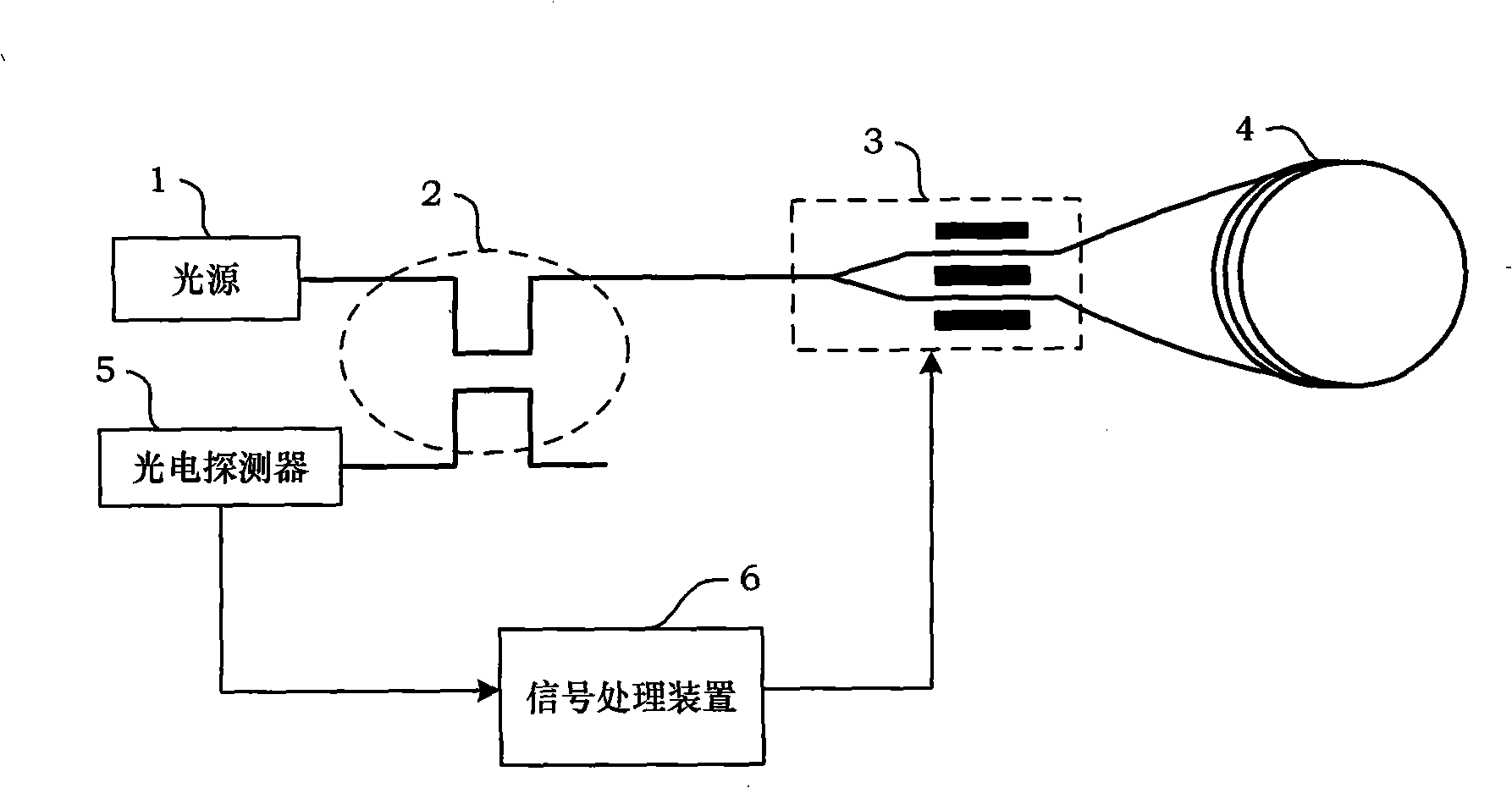
[0026] The present invention will be further described in detail below in conjunction with the accompanying drawings.

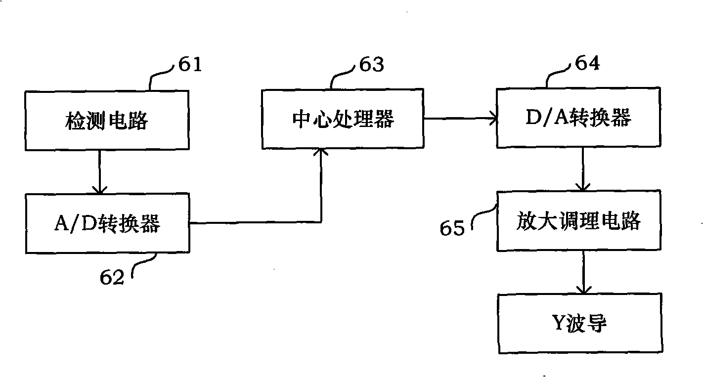
[0027] The present invention is a system for measuring the eigenfrequency and half-wave voltage of an interferometric fiber optic gyroscope using a square wave modulation method. The central processor 63 of the signal processing device 6 in the interferometric fiber optic gyroscope selects an FPGA processor chip of the XC3S400 model.

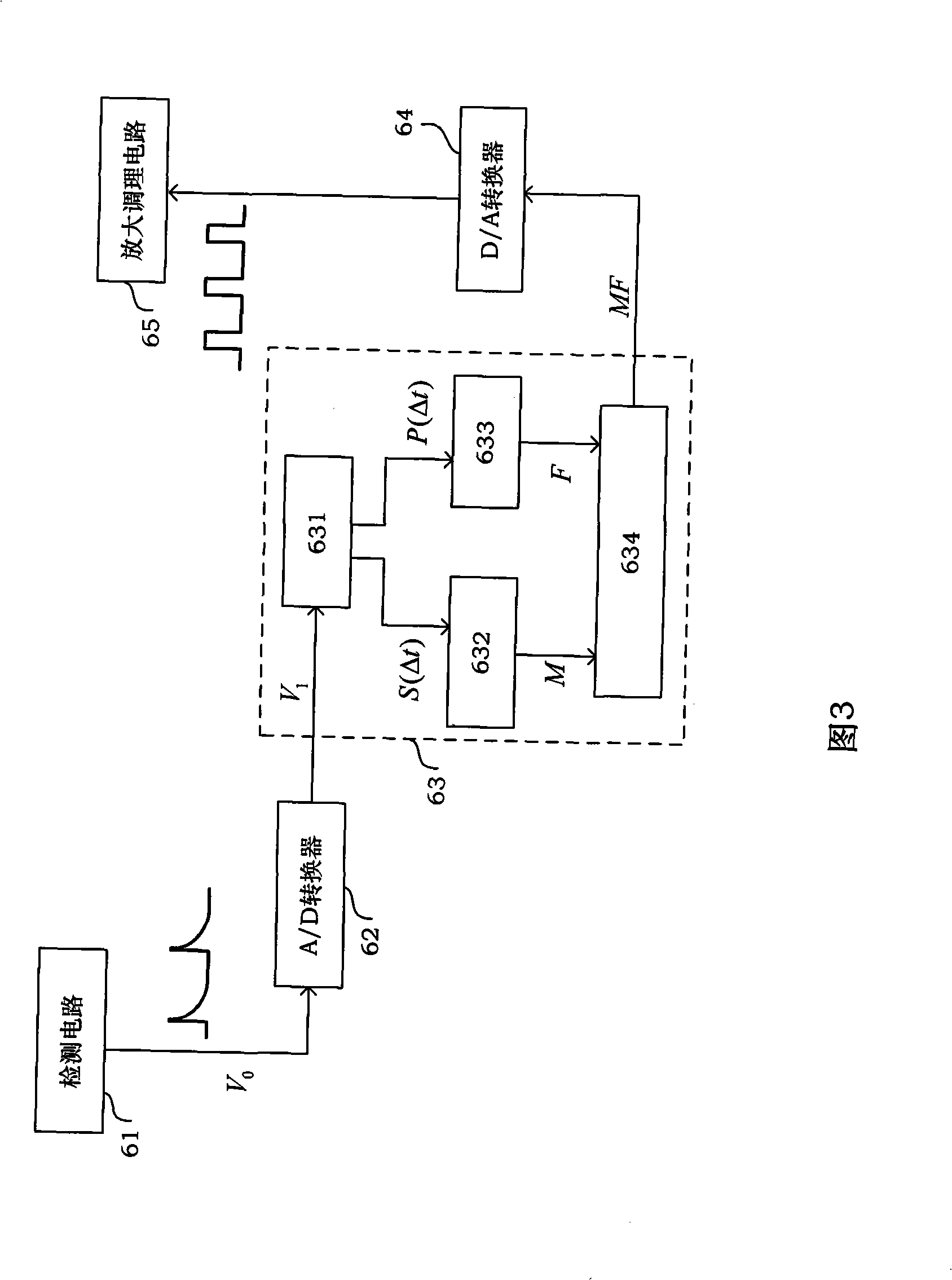
[0028] Referring to FIG. 3 , the central processor 63 is composed of a demodulation unit 631 , a frequency modulation unit 632 , an amplitude modulation unit 633 and a direct digital synthesis unit 634 .

[0029] The demodulation unit 631 is used for (A) from the received optical power information V 1 Extract the effective modulation positive half period Δt within a modulation period ΔT from + The demodulation value P(Δt + ), (B) from the received optical power information V 1 Extract the effective modulation negative half p...


PUM


Abstract

The invention discloses a system adopting square wave to modulate and measure eigen frequency and half-wave voltage of an interferometric fiber-optic gyroscope, wherein a central processor (63) is composed of a demodulation unit (631), a frequency modulation unit (632), an amplitude modulation unit (633) and a direct digital synthesis unit (634); and the demodulation unit (631) is used to (A) extract a demodulation value P(Delta t<+>) of an effective modulation positive half-period Delta t<+>> from received optical power information V1 during a modulation period Delta T, (B) extract a demodulation value P(Delta t<->) of an effective modulation positive half-period Delta t<-> from received optical power information V1 during a modulation period Delta T, (C) average over the demodulation value P(Delta t<+>) of the positive half-period and the demodulation value P(Delta t<->) of the negative half-period to get demodulation average value P(Delta t), and transmit the demodulation average value P(Delta t) to the amplitude modulation unit (633), (D) extract an optical power average value S (Delta t) from received optical power information V1 during a modulation period Delta T and transmit the optical power average value S (Delta t) to the frequency modulation unit (632). The satisfying condition of the modulation frequency fd is 2fe / 5<Fd<8fe / 5, and the satisfying condition of the initial amplitude A0 is Pi / 8<A0< Pi / 2, and the wide range is enough for application in construction.

Description

technical field [0001] The invention relates to a method for measuring the eigenfrequency and half-wave voltage of an interferometric fiber optic gyroscope, more particularly, a method for measuring the eigenfrequency and half-wave voltage of an interferometric fiber optic gyroscope using a square wave modulation method. Background technique [0002] The interferometric fiber optic gyroscope is a sensor for measuring angular rate. The measurement of the angular rate is characterized by the magnitude of the non-reciprocal phase difference caused by the two beams of light propagating in the fiber optic ring in the rotation of the fiber optic gyroscope itself. of. Gyroscopes are devices sensitive to angular motion relative to inertial space. As an important inertial sensor, it is used to measure the attitude angle and angular velocity of the vehicle, and is the core component of the inertial system. It is used in aircraft navigation, ship navigation and land navigation. [0...

Claims


Application Information

Patent Timeline
Patent Type & Authority Applications(China)
IPC IPC(8): G01C19/72G01H13/00G01H17/00
Inventor 宋凝芳张金保金靖马东营唐琦林松
Owner BEIHANG UNIV
Learn More