Sewage treating device and process

A sewage treatment device and packaging technology, applied in the field of water treatment, can solve the problems of low energy consumption per ton of water, high aeration rate, and restrictions on popularization and application.

Active Publication Date: 2008-10-01
BEIJING ECOJOY WATER TECH
View PDF8 Cites 38 Cited by
  • Summary
  • Abstract
  • Description
  • Claims
  • Application Information

AI Technical Summary

Problems solved by technology

Since the bioreactor, which is the main functional unit for removing organic pollutants, still needs an aeration amount corresponding to the air-water ratio of 5-10:1 to complete the carbon oxidation and nitrification process, and the bioreactor also needs aeration as a stirring means To achieve full mixing and contact of sewage, active microorganisms and oxygen, the total aeration volume of the negative pressure external membrane bioreactor is still high, which makes it still have a certain disadvantage in terms of energy consumption per ton of water, especially limited Its popularization and application in large-scale sewage treatment projects

Method used


Image

  • Sewage treating device and process
  • Sewage treating device and process
  • Sewage treating device and process

Examples


Embodiment 1

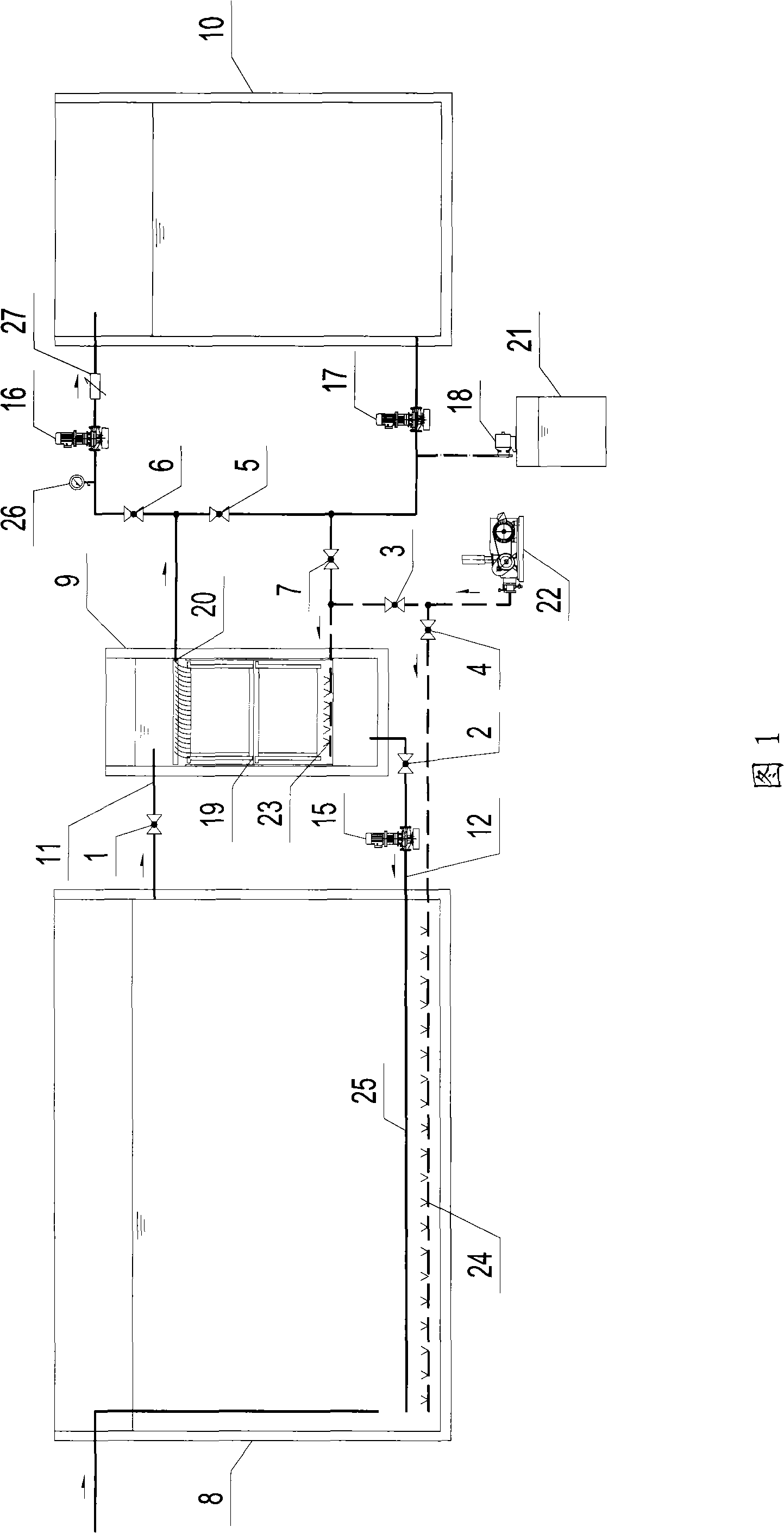
[0073]As shown in Fig. 1 and Fig. 4, a kind of sewage treatment device comprises bioreactor 8, and the membrane filter tank 9 that is independent with biological reactor 8 and co-wall setting, the membrane separation equipment 19 that is installed in the membrane filter tank, The produced water storage tank 10 used to store the permeate of the membrane separation equipment, the activated sludge mixture in the biological reaction tank 8 is transported to the feed liquid supply pipe 11 in the membrane filter tank 9 and the feed liquid supply valve installed on it 1. The position where the feed liquid supply pipe 11 passes through the side wall of the biological reaction tank 8 is located at the top of the side wall but the top of the pipe is 400 mm (mm) lower than the inner water surface, and the position where it passes through the side wall of the membrane filter tank 9 is located at the top of the side wall. The upper part of the side wall but the top of the pipe is 200mm lowe...

Embodiment 2

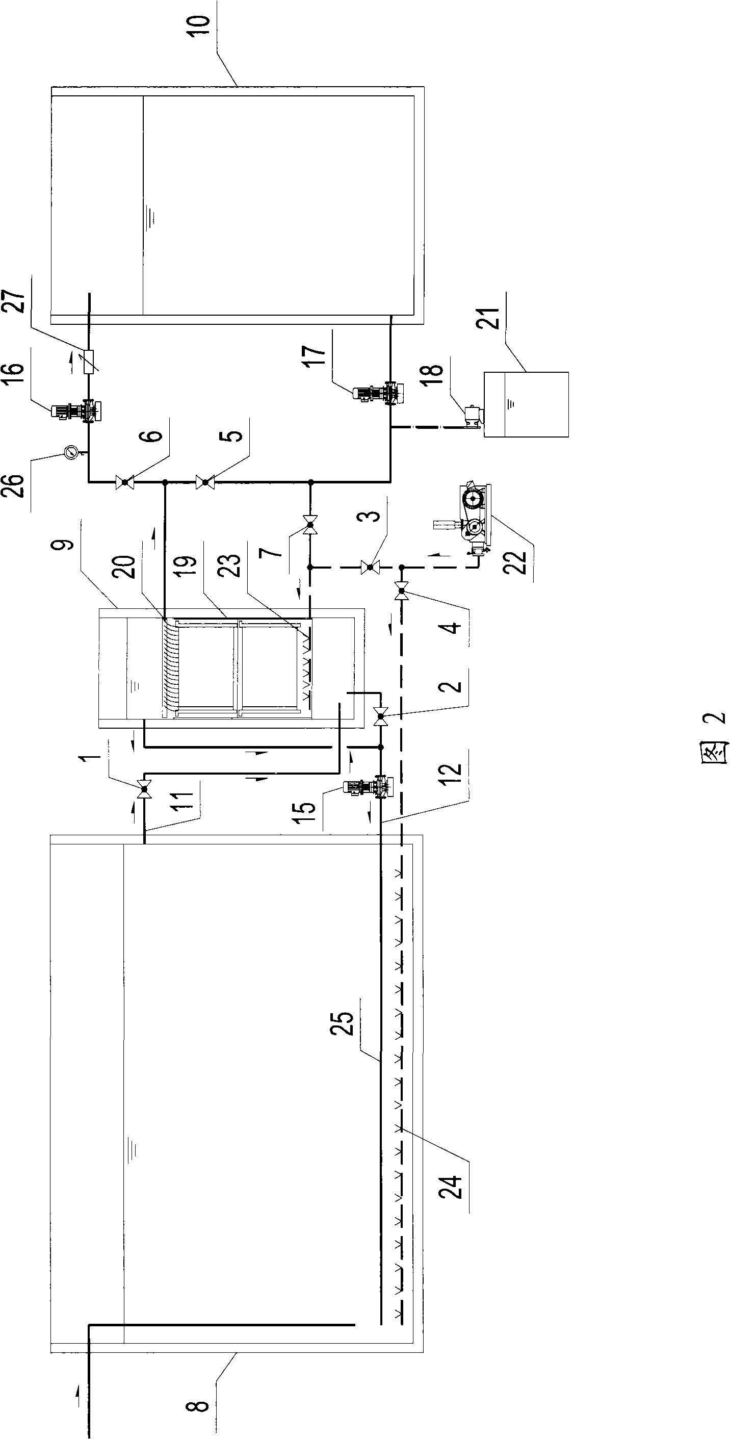
[0085] As shown in Fig. 2 and Fig. 5, a kind of sewage treatment device, most of structure is identical with embodiment 1, the difference is, the activated sludge mixture in the biological reaction tank 8 is transported to the material in the membrane filter tank 9 The position where the liquid supply pipe 11 passes through the side wall of the biological reaction tank 8 is located at the top of its side wall but the top of the pipe is 400mm lower than its inner water surface, and the position where it passes through the side wall of the membrane filter tank 9 is located at the bottom of its side wall but the tube The bottom is 100mm higher than the bottom of the pool, and is positioned below the membrane separation device 19. The feed liquid return pipe 12 that transports the concentrated solution in the membrane filter 9 back to the bioreactor 8 is divided into two branches, one of which passes through the The position of the side wall of the membrane filter tank 9 is located...

Embodiment 3

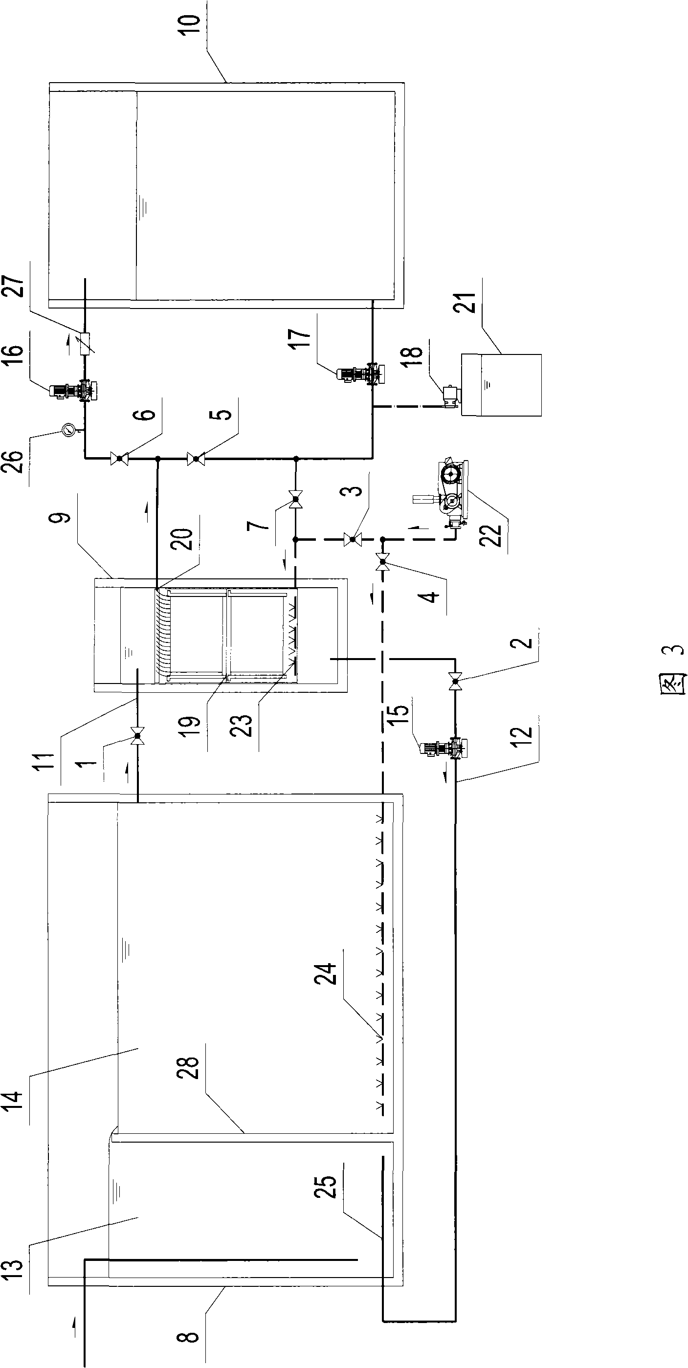
[0092] As shown in Fig. 3 and Fig. 6, a kind of sewage treatment device, most of structure is identical with embodiment 1, difference is, be provided with partition wall 28 in the bioreaction tank 8, partition wall 28 divides bioreaction tank 8 into Only the two parts separated from each other communicated by the top of the partition wall 28, i.e. the anoxic zone 13 and the aerobic zone 14, the volume ratio of the two is 1:3, the bottom of the partition wall 28 is connected with the bottom plate of the biological reaction tank 8 As a whole, there are no holes on the wall, and the top is 200mm away from the water surface. The water distribution device 25 installed at the bottom of the biological reaction tank 8 is only located in the anoxic zone 13, and the 24 gas distribution devices installed in the biological reaction tank 8 are located at the bottom of the biological reaction tank 8. In the aerobic zone 14, the membrane separation equipment 19 and the blower 22 are the same ...


PUM

PropertyMeasurementUnit
pore sizeaaaaaaaaaa
pore sizeaaaaaaaaaa

Abstract

The invention discloses a sewage treatment device which comprises a biological reaction pool and membrane separation equipment. The membrane separation equipment is arranged outside the biological reaction pool, the interior of which is provided with mixing equipment. The interior of the membrane separation equipment or the interior of the container that holds the membrane separation equipment isprovided with aeration equipment, and the membrane separation equipment or the container that holds the membrane separation equipment is communicated with the biological reaction pool through a pipeline. The interior of the membrane separation equipment is provided with the mixing equipment in the invention, and leads the concentrated solution which reflows through the membrane separation equipment or the container that holds the membrane separation equipment to be fully mixed with the mixing solution in the biological reaction pool, thereby avoiding the wasting phenomenon of energy consumption caused by high strength aeration in a membrane filter pool, which is common in existing negative pressure external membrane bioreactors; therefore, the gas-water ratio of the membrane bioreactor isgenerally reduced to 12:1 and even less than 10:1, which is basically close to other sewage biological treatment techniques of a traditional active sludge method, etc., thus leading the energy consumption in operation of a sewage treatment system to be maintained at a relatively low level.

Description

technical field [0001] The invention relates to a sewage treatment device and process, in particular to a sewage treatment device and process using a membrane bioreactor process, belonging to the technical field of water treatment. Background technique [0002] The membrane bioreactor (Membrane Bioreactor, MBR) process is an efficient sewage treatment and reuse technology that organically combines membrane separation technology and traditional biological treatment technology. In the membrane bioreactor system, all kinds of pollutants in the sewage are mainly removed through the biochemical action of microorganisms, but different from the traditional biological treatment process, the membrane separation equipment replaces the secondary sedimentation tank to make the muddy water Complete separation, which makes SRT (sludge retention time or biological solid retention time) and HRT (hydraulic retention time) can be controlled independently of each other, the increase of activat...

Claims


Application Information

Patent Timeline
Patent Type & Authority Applications(China)
IPC IPC(8): C02F9/14C02F1/44
CPCC02F3/302B01D2315/06B01D63/06B01D63/082B01D2313/20C02F2303/16C02F3/308C02F2209/22B01D61/18C02F3/1268C02F2209/04B01D63/08B01D2313/50B01D61/08Y02W10/10
Inventor 孙友峰
Owner BEIJING ECOJOY WATER TECH
Why Eureka
Try Eureka