Underwater blast wave field test system

A test system and shock wave technology, applied in the transmission system, vibration measurement, measuring device, etc., can solve the problems of inconvenient layout, low signal-to-noise ratio, and limited use conditions, etc., and achieve simple layout, high signal-to-noise ratio, and small size Effect

Inactive Publication Date: 2008-10-15
ZHONGBEI UNIV
View PDF0 Cites 14 Cited by
  • Summary
  • Abstract
  • Description
  • Claims
  • Application Information

AI Technical Summary

Problems solved by technology

[0004] The purpose of the present invention is to provide the society with a small-scale integrated underwater shock wave field test system, which can solve the p

Method used


Image

  • Underwater blast wave field test system
  • Underwater blast wave field test system
  • Underwater blast wave field test system

Examples


Embodiment 1

[0018] Embodiment 1. Underwater shock wave field test system

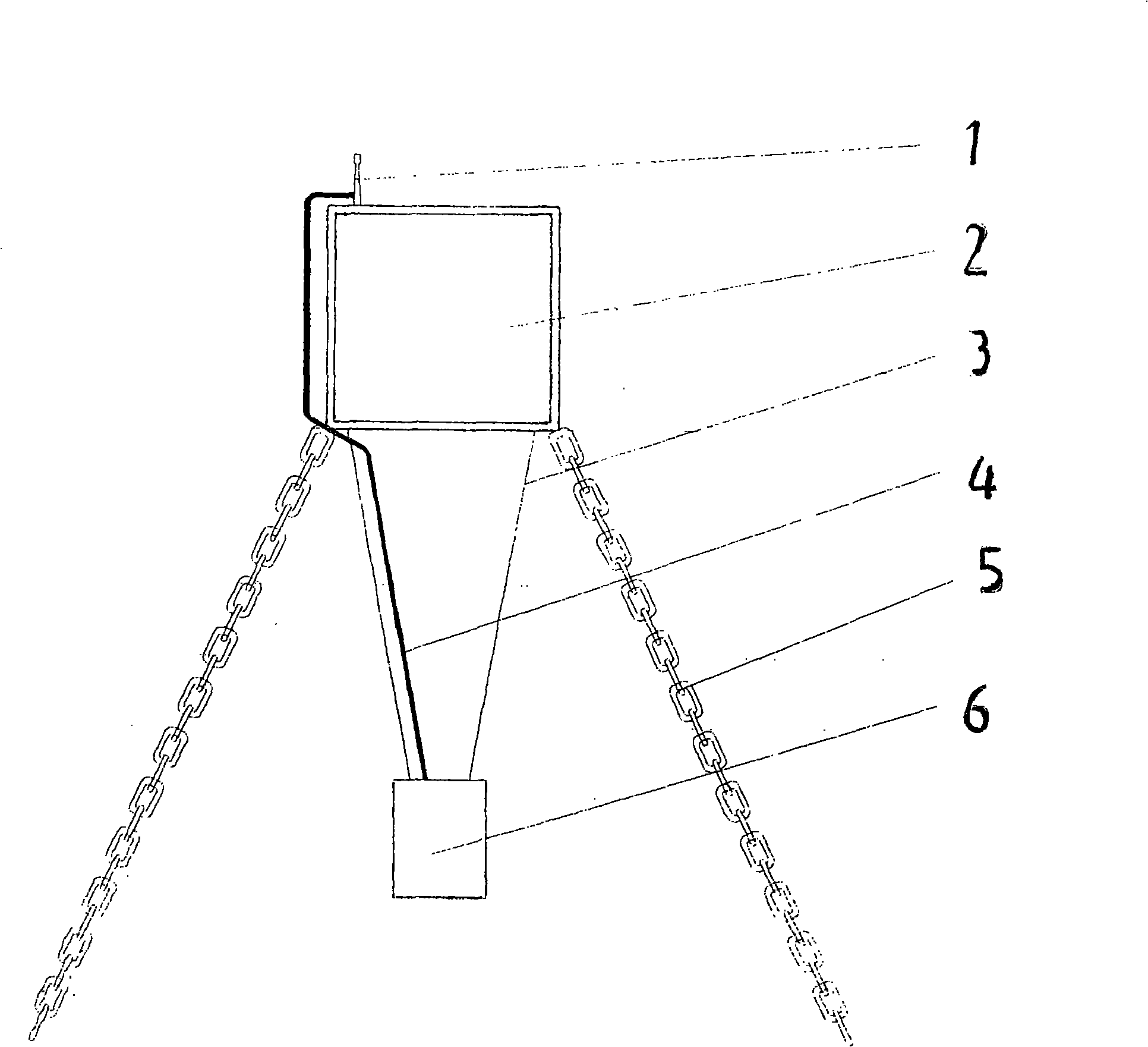
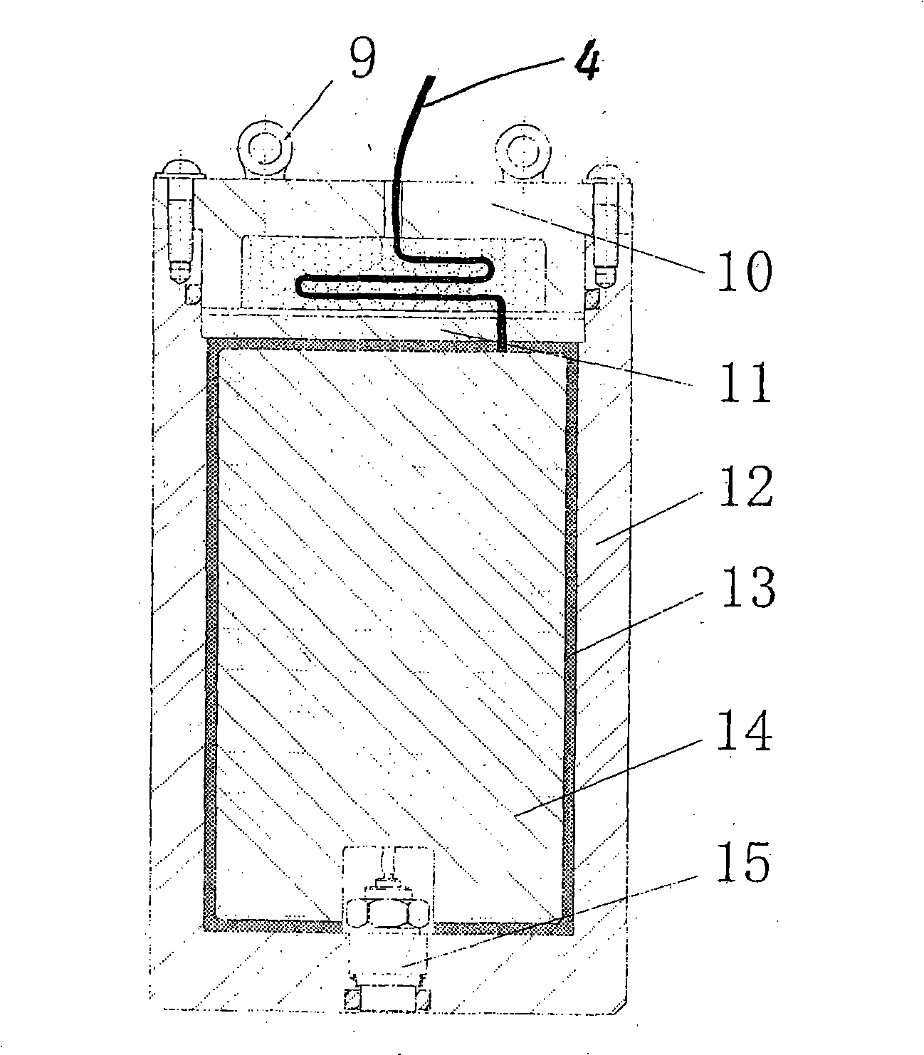
[0019] The specific structure of the underwater shock wave field test system in this example is given by Figure 1 ~ Figure 3 Jointly shown. figure 1 Middle: 1 is the transmitting antenna, 2 is the buoy, 3 is the suspension steel wire, 4 is the waterproof and impact-resistant cable, 5 is the positioning anchor, 6 is the electronic tester, a test station is composed of 1 to 6, such a test station can be There are multiple or several, and the test station can be provided with one, or two, or three digits of Arabic numerals according to the needs, and multiple points form an underwater shock wave test field. The buoy 2 can be made into a metal box, brushed with waterproof paint inside and outside, and its volume is determined by the weight of the electronic tester 6 and the weight of the buoy 2 itself. The two positioning anchors 5 protruding from the bottom of the buoy 2 are fixed underwater, so that each test stat...

Embodiment 2

[0020] Embodiment 2. Underwater shock wave field test system

[0021] The general structure of the underwater shock wave field test system in this example can be Figure 1 ~ Figure 3 etc. jointly show that the underwater shock wave field test system of this example is different from Embodiment 1: 1. each functional electronic circuit of the electronic tester of the underwater shock wave field test system of this example can be designed with known and public techniques And make, as long as they can finish its function all can adopt; 2. the circuit module that each functional electronic circuit of the electronic tester of this example adopts, pressure sensor etc. can be designed with known public technology, also can use known , public, and commercially available commodity substitutions, as long as they can complete their functions, they can be used. The rest of the underwater shock wave field testing system in this example is the same as that described in Embodiment 1 and will n...


PUM


Abstract

The invention discloses an underwater shockwave field testing system which consists of a master control station and a plurality of testing stations. The test of an underwater shockwave field is completed in a mode of real-time acquisition and storage and post-wireless transmission; each testing station adopts a pressure sensor and an integrated dynamic overvoltage electron tester integrated by signal acquisition, processing, storage and wireless transmission modules and other circuit modules; the pressure sensor and the integrated dynamic overpressure electron tester are fixed on each testing point by positioning anchors and buoys; the master control station consists of a wireless transmission module, a computer, etc. Before the testing is carried out, parameter setting and performance detection are carried out to each testing station; after the testing is carried out, test data is transmitted; the testing system has the characteristics of real-time acquisition and record, post-transmission, repeatable triggering, repeated use, etc; and the testing system has small size, strong antijamming capability, high noise-signal ratio, simple arrangement and convenient use and is suitable for underwater shockwave field testing systems in various water areas.

Description

1. Technical field [0001] The underwater shock wave field test system disclosed by the invention belongs to the technical field of shock wave test, and specifically relates to an integrated underwater shock wave field test system, which can meet the underwater shock wave field test requirements of various water areas. 2. Background technology [0002] Weapons such as mines, torpedoes, depth charges, aerial bombs, and missiles release huge energy at the moment of explosion in water, forming superheated and high-pressure bubbles, and generating strong shock waves in the surrounding waters. The ship in the explosion field will be strongly affected by the transient shock wave in the water and the pulsating pressure of the bubbles, which will cause serious damage to the local or overall structure of the ship, resulting in the consequences of ship sinking and death. Underwater personnel or animals will also suffer from various injuries due to the shock wave. Underwater shock wave...

Claims


Application Information

Patent Timeline
IPC IPC(8): G01H3/00G01L9/00H04B13/02
Inventor 祖静杜红棉王代华王文廉王巍范锦彪张志杰马铁华
Owner ZHONGBEI UNIV
Why Eureka
Try Eureka