
Tooth geometrical shape measurement device

A technology of geometric shape and measuring device, applied in the directions of diagnostic recording/measurement, dentistry, medical science, etc., can solve the problems of reducing the resolution of digital images of teeth, highly blurred digital images of teeth, and uncertainty of digital image data, etc. Achieve improved measurement sensitivity and accuracy, shadow avoidance, high mesh geometry image resolution

Inactive Publication Date: 2008-10-22
宁波思达利光电科技有限公司
View PDF0 Cites 11 Cited by
  • Summary
  • Abstract
  • Description
  • Claims
  • Application Information

AI Technical Summary

Problems solved by technology

However, this device has obvious disadvantages: a) Due to the coherence of light, the phase-shift analysis technology using sinusoidal gratings is severely limited by the speckle situation, resulting in highly blurred digital images of teeth; b) the device passes filtering or Smoothing technology reduces or eliminates the background noise and intensity disturbance of linear stripes, but at the same time greatly reduces the resolution of digital images of teeth; c) Phase shift analysis technology is applied to fixed parallel grids, when the height of teeth changes suddenly (greater than 2π difference) will cause the linear fringe shift to be greater than the grid distance, and more projections or changing the grid distance are required to compensate for this defect, which makes the structure of the device more complicated, and at the same time causes the uncertainty of digital image data
[0003] In addition to the above-mentioned shortcomings, optical measurement devices including the above-mentioned CEREC device have a common defect. Since the parallax angle is a very important parameter, the larger the parallax angle is, the higher the sensitivity of the measurement is, but at the same time the shadow problem is more serious , in order to eliminate shadows as much as possible, the optical measurement device usually chooses a parallax angle less than 10°, or even smaller, but this greatly reduces the measurement accuracy of teeth

Method used


Image

  • Tooth geometrical shape measurement device
  • Tooth geometrical shape measurement device
  • Tooth geometrical shape measurement device

Examples


Embodiment 1

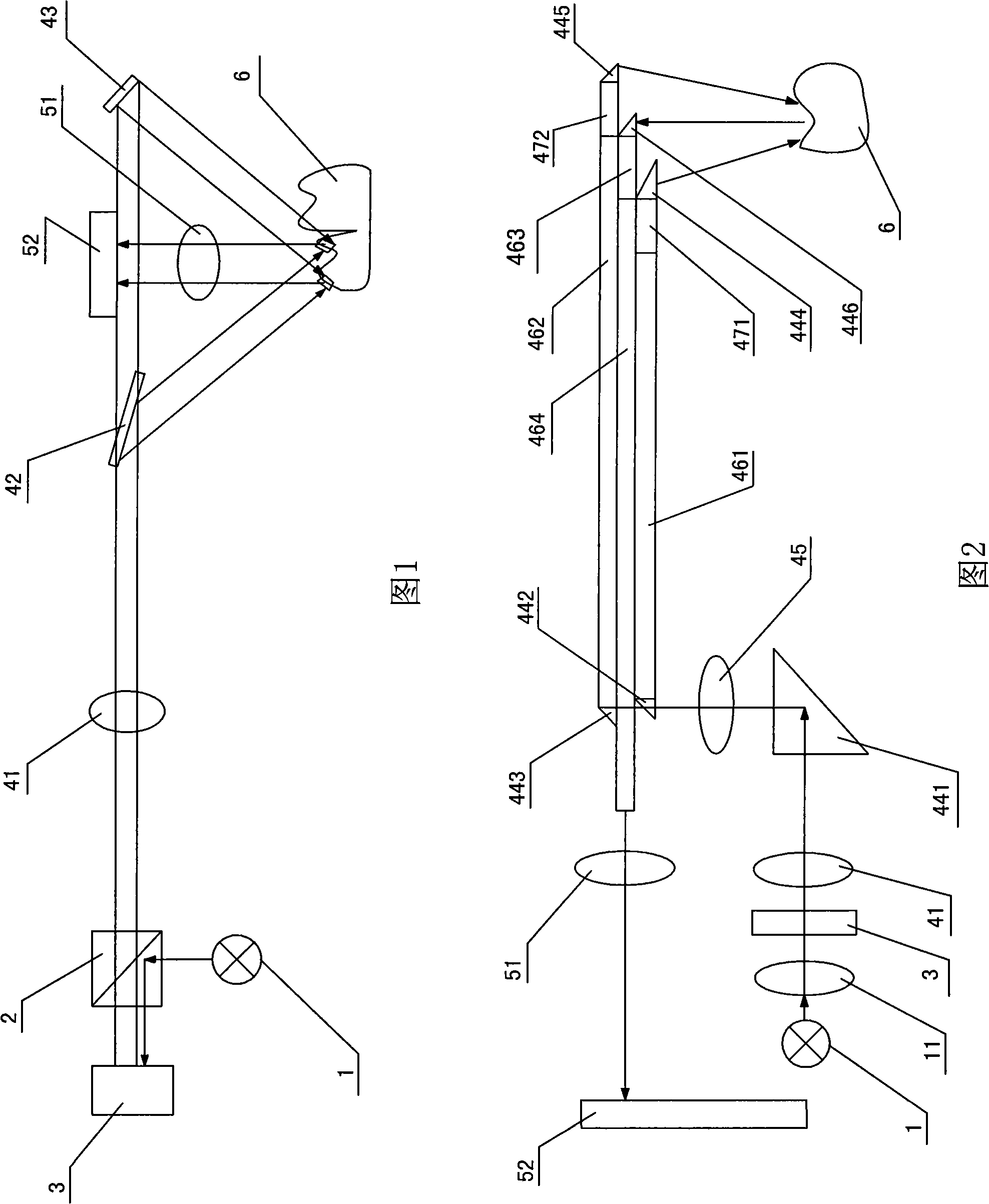
[0019] Embodiment one: as shown in Figure 1, a kind of tooth geometry measuring device, this device comprises light source 1, image generation unit, projection unit and imaging unit; Image generation unit comprises the programmable pattern generator 3 and polarization Dichroic prism 2, the projection unit includes projection lens 41, variable polarization beam splitter 42 and reflector 43, variable polarization beam splitter 42 and reflector 43 are distributed on both sides of the imaging unit, and the imaging unit includes imaging lens 51 and imaging camera 52 , the incident light emitted by the light source 1 is irradiated on the programmable pattern generator 3 through the polarizing beam splitter prism 2, and the programmable pattern generator 3 generates a mesh geometric pattern image, and outputs the polarized mesh geometric pattern image through the polarizing beam splitter prism 2, and then The polarized mesh geometric image is transmitted to the variable polarization b...

Embodiment 2

[0025] Embodiment two: as shown in Figure 2, the difference between this embodiment and embodiment one is only that the image generation unit includes a programmable pattern generator 3 connected to an external computer, and the light source 1 and the programmable pattern generator 3 are provided with The illumination lens 11, the projection unit includes a projection lens 41, a first prism 441, a scanning lens 45, a second prism 442, a third prism 443, a first gradient lens 461, a second gradient lens 462, a first gradient lens objective lens 471, a fourth gradient lens Prism 444, the second gradient lens objective lens 472 and the fifth prism 445, the imaging unit includes the sixth prism 446, the third gradient lens 463, the fourth gradient lens 464, imaging lens 51 and imaging camera 52, the second prism 442 is a polarization splitter Prism; the incident light emitted by the light source 1 is irradiated on the programmable pattern generator 3 through the illumination lens 1...


PUM


Abstract

The invention discloses a tooth geometrical shape measuring device, which comprises a light source, an image generating unit, a projector unit and an imaging unit. The light source sends out incoming ray to irradiate on the image generating unit; the image generating unit produces network geometric figure images; the projector unit alternately projects the network geometric figure images with the same shape on the teeth surface in a symmetrical triangle angle to form different twisty network geometric figure images; two different twisty network geometric figure images are reflected in the imaging unit by the teeth surface and transferred to the outside computer; the prospective angle between the projecting optical lines projected by the projector unit and the imaging optical lines reflected by the teeth surface ranges from plus / minus 10 degrees to plus / minus 30 degrees. The measuring device is characterized in that the LCOS is adopted and only needs lower driving pressure, and the LCOS can produce any images used for computer imaging algorithm, at the same time, the LCOS leads the network geometric figure images to have higher resolution.

Description

technical field [0001] The invention relates to an optical measurement device, in particular to a tooth geometry measurement device. Background technique [0002] At present, there are many optical measurement devices for the teeth in the patient's oral cavity, such as the CEREC (Chair-side Economic Reconstruction of Esthetic Ceramic, digital clinical restoration system) device manufactured by Sirona Company, which was separated from Germany's Siemens. The graphic projection industrial measurement technology projects the parallel grid of light and dark linear stripes on the surface of the tooth, and images them on the two-dimensional CCD (Charge Coupled Device, Charge Coupled Device) camera at a parallax angle. The relative height or relative depth of the tooth can be obtained from the curvature, and the digital image data of the tooth is processed by using the phase shift or phase analysis technology of the sinusoidal grating; wherein, the phase of the linear fringe is move...

Claims


Application Information

Patent Timeline
Patent Type & Authority Applications(China)
IPC IPC(8): A61B5/107A61C19/04
Inventor 罗南丁洪李同
Owner 宁波思达利光电科技有限公司
Learn More