
Light circulator based on space-free directional coupled structure

A technology of directional coupling and optical circulator, which is applied in the coupling direction of optical waveguide, etc., can solve the problems that the device has not been developed, and achieve the effect of compact structure and high integration

Inactive Publication Date: 2008-10-22
ZHEJIANG UNIV
View PDF0 Cites 2 Cited by
  • Summary
  • Abstract
  • Description
  • Claims
  • Application Information

AI Technical Summary

Problems solved by technology

However, as an integrated optical optical isolator, it is still in the prototype research stage of the laboratory, and practical devices have not yet been developed.

Method used


Image

  • Light circulator based on space-free directional coupled structure
  • Light circulator based on space-free directional coupled structure
  • Light circulator based on space-free directional coupled structure

Examples


Embodiment 1

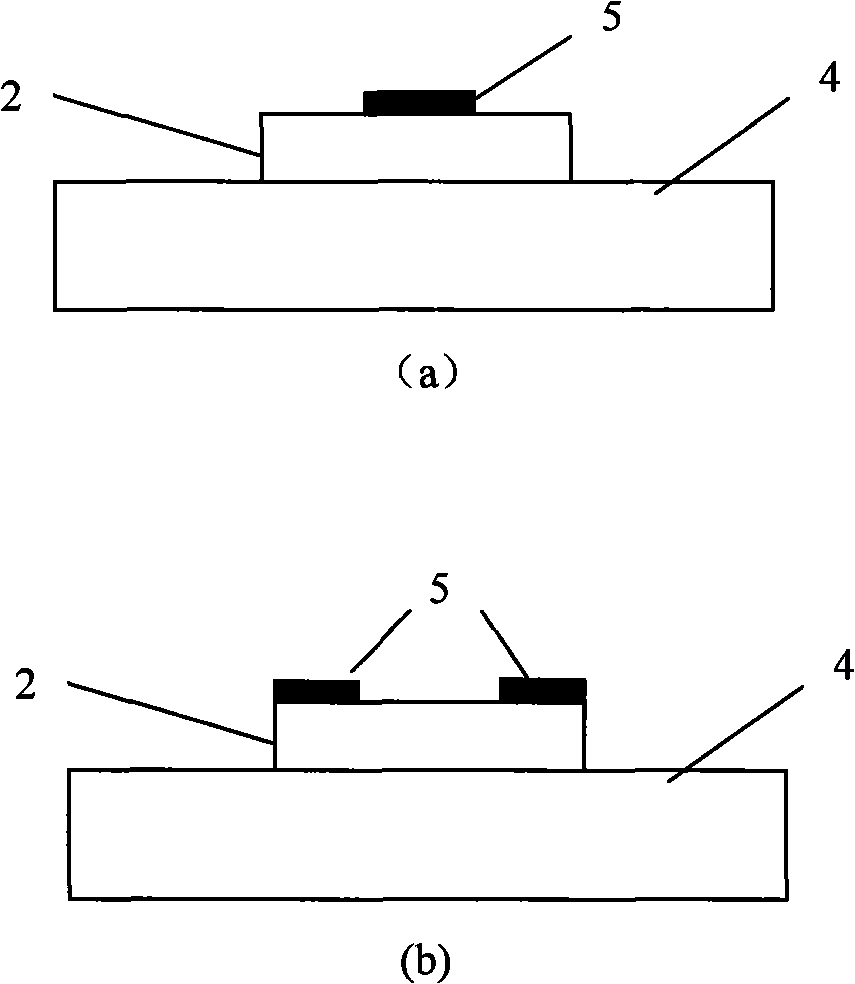
[0031] In the manufacture of devices, a layer of non-magnetic metal film or dielectric film is grown on the dielectric substrate, and then the rectangular dual-mode waveguide is fabricated by chemical wet etching or reactive ion etching, and then the rectangular dual-mode waveguide is used on the rectangular dual-mode waveguide area. Local bonding or sputtering methods to prepare centers (eg figure 2 (a)) or central symmetry (such as figure 2 As shown in (b), a magnetic material thin film 5 is provided.

Embodiment 2

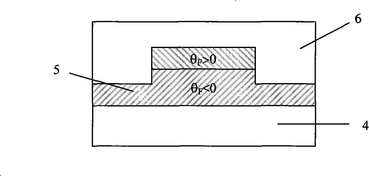
[0033] A thin film of magnetic material is grown on the substrate, and then the waveguide is fabricated by chemical wet etching or reactive ion etching, and a cladding layer 6 with a large difference in refractive index from the substrate can also be grown on it, such as image 3 shown.

[0034] In order to enhance the non-reciprocal phase shift and realize more compact optical isolators and optical circulators, it is also possible to use another layer of Faraday rotation coefficient θ on the magnetic material film F On the contrary, a thin film of magnetic material is used to fabricate a waveguide by chemical wet etching or reactive ion etching. like image 3 The Faraday rotation coefficient θ shown in F >0 at the Faraday rotation coefficient θ F F F >0 below.


PUM


Abstract

The invention discloses an optical circulator based on a non-spacing directional coupling structure. The invention is formed by orderly and serially connecting an input Y-branch waveguide, a rectangular dual-mode waveguide provided with magnetic material, and an output Y-branch waveguide on a substrate. The proposal of the invention is to adopt the non-spacing directional coupling structure and utilize the non-reciprocal phase shift difference principle of a basic mode and a one-off pattern thereof to realize the integration of an optical isolator and the optical circulator through the non-reciprocal phase shift. The non-reciprocal device has the characteristics of compact structure and high integration level, has application prospect in aspects such as emission, amplification, transmission, and routing of light signals and so on, and has scientific research significance and application value.

Description

technical field [0001] The invention relates to a device for controlling the direction of light, in particular to an optical circulator based on a directional coupling structure without spacing. Background technique [0002] In optical information systems such as optical fiber communication, the connection of different devices often reflects a part of the light. Once the reflected light enters the cavity of the laser source, it will cause parasitic oscillation of the light source, affect the frequency stability of the light source, and limit its modulation bandwidth. Thereby limiting the improvement of the overall system performance. Optical isolator (Optical Isolator) is a magneto-optical non-reciprocal device specially developed to solve this problem. So far, practical optical isolators include bulk optical isolators using bulk garnet crystals as Faraday rotators and micro-optical devices with reduced size. However, as an integrated optical optical isolator, it is still ...

Claims


Application Information

Patent Timeline
Patent Type & Authority Applications(China)
IPC IPC(8): G02B6/26
Inventor 孙一翎江晓清周海峰杨建义郝寅雷周强李锡华王明华
Owner ZHEJIANG UNIV
Learn More