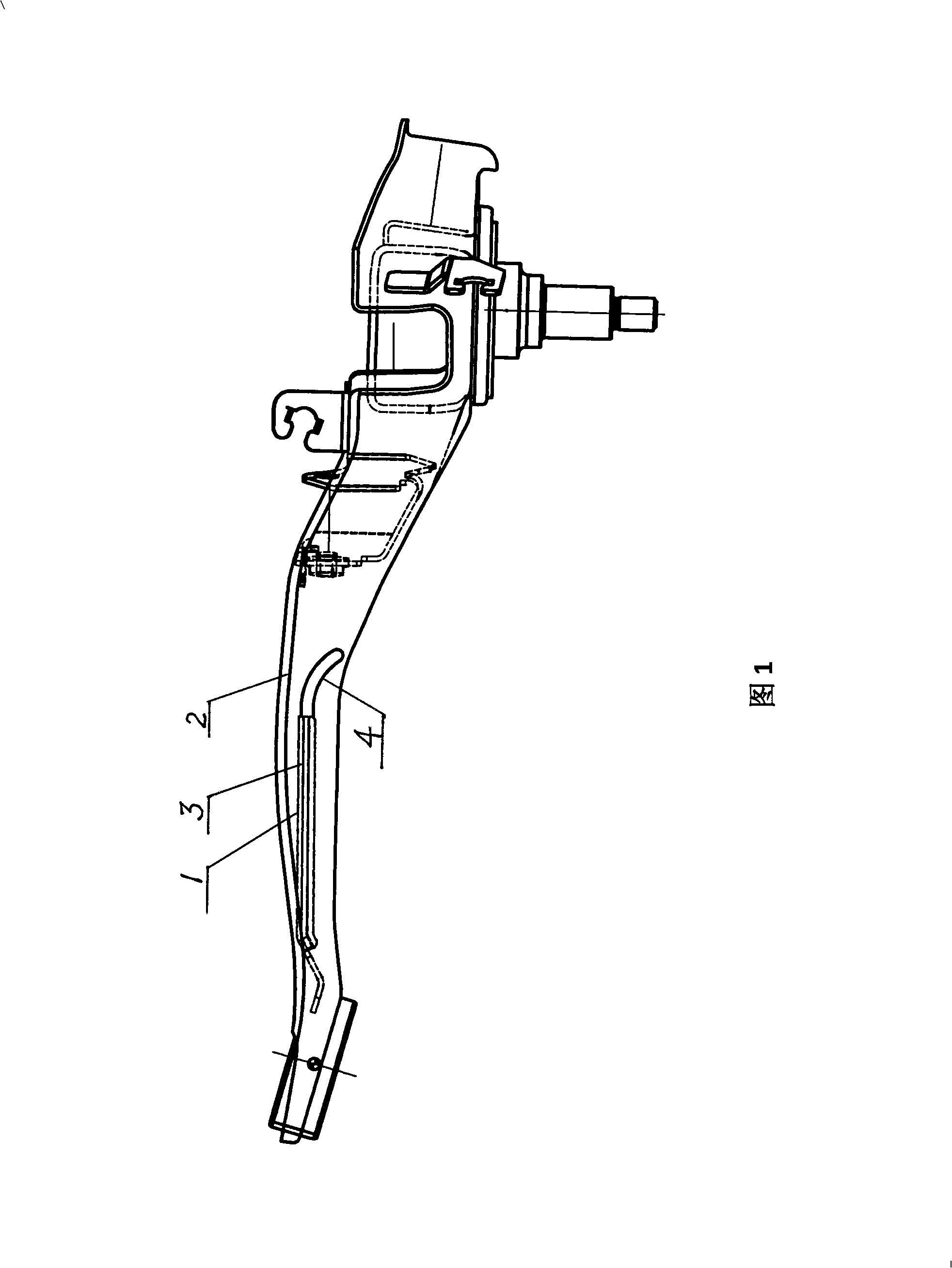
Welding process for rear overhang rack

A welding process and rear suspension technology, which is applied to suspensions, vehicle parts, cantilevers mounted on pivots, etc., can solve the problems of difficult heat treatment of drag arm components, ignoring welding heat-affected zones, ignoring stress concentration points, etc. , to achieve the effect of easy control of quality, reduction of heat treatment process, and elimination of welding residual stress

Inactive Publication Date: 2008-10-29
SHANGHAI ZHONGLI AUTO PARTS
View PDF0 Cites 6 Cited by
  • Summary
  • Abstract
  • Description
  • Claims
  • Application Information

AI Technical Summary

Problems solved by technology

[0007] 1. The stress concentration point is ignored during the test loading;
[0008] 2. The welding heat affected zone is ignored;
[0012] It is generally believed that the residual stress of welding is equivalent to the average stress, and the tens

Method used


Image

  • Welding process for rear overhang rack

Examples


Embodiment

[0021] As shown in Figure 1, it is a schematic diagram of the welding structure of a rear suspension of an automobile. The welding process of the rear suspension of an automobile is as follows: the reinforcing plate 1 is welded with the trailing arm 2, and then welded at the joint of the weld 3 Transition to the bottom edge of the drag arm 2 with a smooth arc 4, the length of the arc 4 is 43mm, the radius of the arc is 35mm, the weld width is 7mm, and all welding parameters are the same as the original welding.

[0022] The welded rear suspension of the automobile did not break after reaching the required number of fatigue times during the suspension fatigue test.


PUM

PropertyMeasurementUnit
Lengthaaaaaaaaaa
Radiusaaaaaaaaaa
Widthaaaaaaaaaa

Abstract

The invention relates to a welding technique of a back suspension fork of an automobile; a reinforced plate is connected with a dragging arm; the invention is characterized in that the head part of a welding line is welded with a smooth arc and then is transited to the bottom side of the dragging arm; the welding technique of the invention has the advantages of removing the heat treatment after the welding and eliminating welding residual stress of the welding joint of the reinforced plate, thereby simplifying the technique during manufacture, being easy to control the quality, improving the fatigue strength of a product and reducing the manufacturing cost.

Description

technical field [0001] The invention relates to a welding process of an automobile rear suspension, in particular to a welding process of an automobile rear suspension-trailing arm, which further improves the fatigue strength of the suspension system and belongs to the technical field of welding processes. Background technique [0002] In China, in order to meet the requirements of a car chassis and increase the strength of the rear suspension-trailing arm, a reinforcing plate is added to the rear suspension-trailing arm of the car, and the reinforcing plate and the trailing arm are welded. [0003] The welding process between the reinforcement plate and the drag arm body has the following characteristics: [0004] 1. When the reinforcing plate and the dragging arm are welded, the starting and closing positions of the arc are sealed and welded; [0005] 2. When welding the reinforcing plate and the dragging arm, there is a margin of 12mm between the starting and ending posi...

Claims


Application Information

Patent Timeline
IPC IPC(8): B60G7/00
Inventor 魏彬
Owner SHANGHAI ZHONGLI AUTO PARTS
Why Eureka
Try Eureka