Solenoid valve diagnosis detecting method and device for electric-controlled co-rail fuel feed pump

A detection method and solenoid valve technology, applied in measurement devices, fuel injection devices, charging systems, etc., can solve problems affecting engine performance, inappropriate diagnosis and detection, and inconspicuous characteristic points of the driving current waveform of the injector solenoid valve, etc. problems, to achieve the effect of improved performance and reliability, low manufacturing cost, and improved consistency

Inactive Publication Date: 2008-10-29
CHINA FIRST AUTOMOBILE
View PDF2 Cites 34 Cited by
  • Summary
  • Abstract
  • Description
  • Claims
  • Application Information

AI Technical Summary

Problems solved by technology

At the same time, the solenoid valve is also a key component of the common rail injection system, and its performance directly affects the pressure control and stability of the common rail system, which in turn affects the performance of the engine.
[0003] Among the existing patents on electronically controlled common rail injection systems for diesel engines, there are many patents on diagnosis and judgment standards for solenoid valves of electronically controlled fuel injectors. For example, Chinese patent CN1450452A discloses a method and device for running-in diagnosis of switch solenoid valves for electronically controlled diesel engines. , this method proposes a diagnosis and judgment method and device for the high-speed and powerful solenoid valve of the fuel injector, and judges whether the solenoid valve meets the performance requirements according to the current value within a specific period of time, but the current waveform characteristi...

Method used


Image

  • Solenoid valve diagnosis detecting method and device for electric-controlled co-rail fuel feed pump
  • Solenoid valve diagnosis detecting method and device for electric-controlled co-rail fuel feed pump
  • Solenoid valve diagnosis detecting method and device for electric-controlled co-rail fuel feed pump

Examples


Embodiment Construction

[0018] The working principle, specific structure and preferred embodiments of the fuel pump electromagnetic valve diagnosis and detection method and device of the present invention will be described in detail below in conjunction with the accompanying drawings.

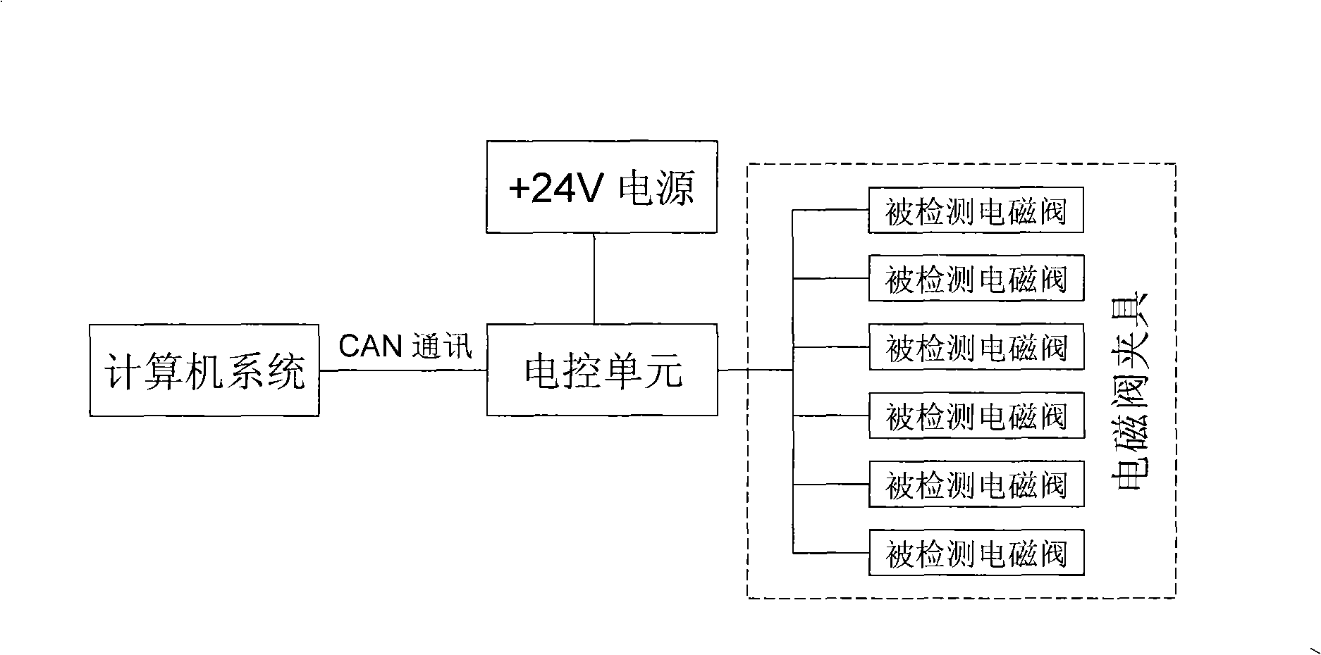
[0019] figure 1 It is a schematic system block diagram of an embodiment of the diagnostic detection device for the solenoid valve of the fuel supply pump in the present invention, which includes a PC, an electronic control unit, a +24V power supply and a solenoid valve to be detected, and can simultaneously detect 6 solenoid valves at a time, and the electric control unit CAN communication is used to exchange and analyze measurement data with the PC.

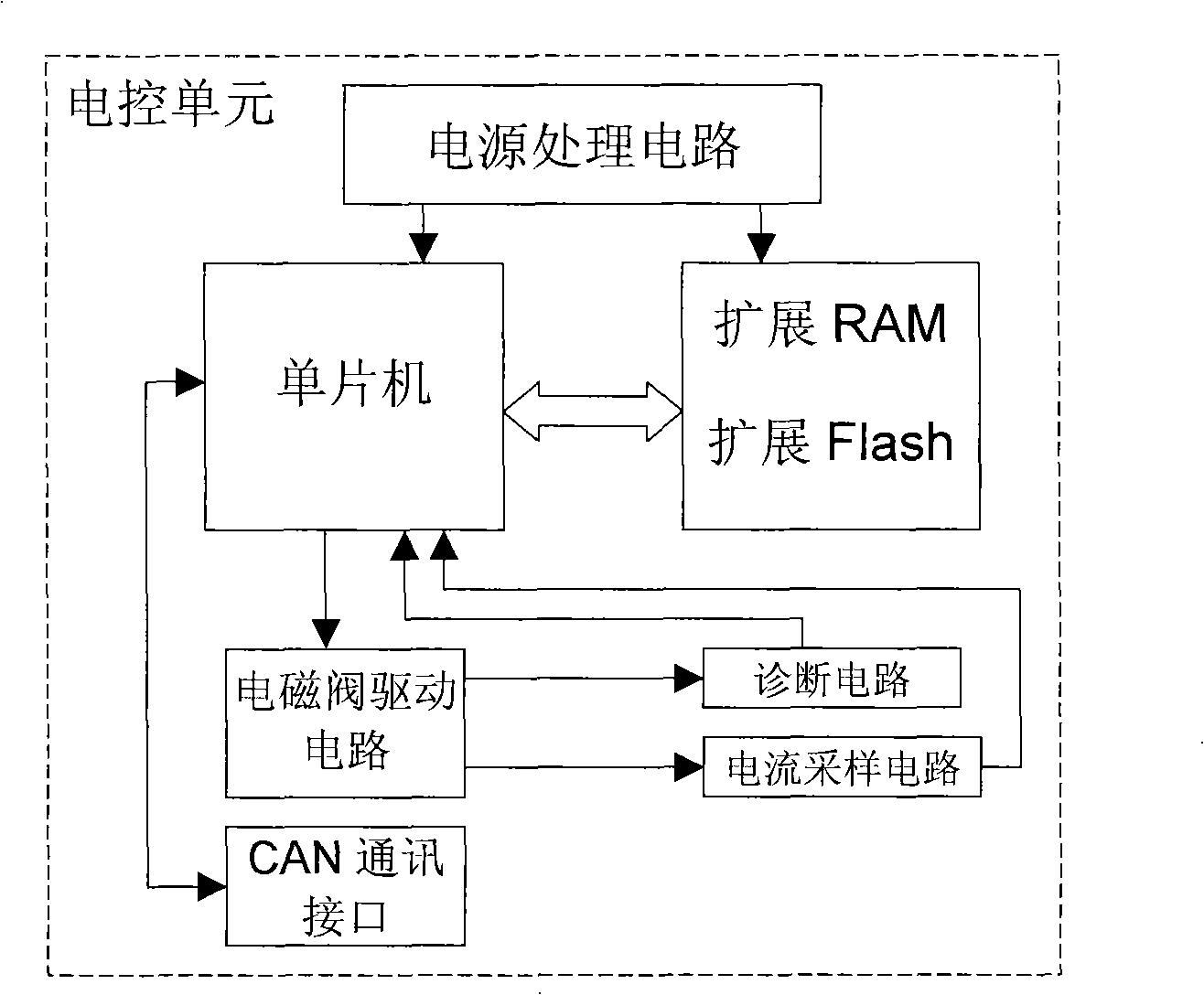
[0020] figure 2 It is a block diagram of the hardware structure connection of the electronic control unit in the electromagnetic valve detection device, mainly including a single-chip microcomputer. The model selected in this embodiment is Infineon's C167-CR, external...


PUM


Abstract

The invention relates to a diagnosis and detection method and a device for an electromagnetic valve used for an electrically controlled common rail fuel feed pump. The method is characterized in that control parameters predetermined by test is input by a monitor program, current waveform during the drive of the electromagnetic valve is detected in real time and curve fitting is conducted; accordingly, the characteristics of the electromagnetic valve are judged, the movement circumstances when turning-on and shutting-down of the electromagnetic valve delays are measured and then whether the electromagnetic valve has the fault of deadlocking or open circuit can be analyzed. When the electromagnetic valve diagnosis and detection device is in use, no fuel injection pump test stand is needed; the use of the device can improve the consistence of the performance of the fuel feed pump electromagnetic valve, thereby greatly improving the performance and reliability of a common rail fuel injection system. The electromagnetic valve detection device has the advantages of low manufacture cost, convenient use, good self-diagnostic function and easy implementation in mass production.

Description

technical field [0001] The invention relates to a method and a device for diagnosing and detecting an electromagnetic valve for an electronically controlled common rail system of a diesel engine, in particular to a method and a device for diagnosing and detecting an electromagnetic valve for an electronically controlled common rail oil supply pump. Background technique [0002] The solenoid valve for the high-pressure oil supply pump of the common rail system is an outward-opening solenoid valve. By changing the oil supply starting point of the oil supply pump, the oil supply volume of the plunger of the oil supply pump is controlled to achieve the purpose of controlling the common rail pressure of the system. The switching times of the solenoid valve of the fuel supply pump during work are directly proportional to the speed of the high-pressure fuel supply pump of the engine. Therefore, the solenoid valve needs to withstand the impact of high-frequency pulse current and mech...

Claims


Application Information

Patent Timeline
IPC IPC(8): F02M65/00
Inventor 宋国民胡林峰陆召振谢宏斌张爱云高巍
Owner CHINA FIRST AUTOMOBILE
Why Eureka
Try Eureka