Catalyst distillation column internals for high effective mass transfer

A technology for catalytic distillation towers and tower internals, applied in distillation separation, chemical instruments and methods, chemical/physical processes, etc., can solve problems such as gas short circuit, low reaction efficiency, difficult coupling of reaction and separation, etc., and achieve control of residence time , to avoid the effect of overreaction

Active Publication Date: 2008-11-19
TIANJIN UNIV
View PDF7 Cites 14 Cited by
  • Summary
  • Abstract
  • Description
  • Claims
  • Application Information

AI Technical Summary

Problems solved by technology

However, due to the large void ratio of the tower internals, there is a serious gas short circuit phenomenon. When the gas with a very low content of effective components is used as the catalytic distillation system, the reaction efficiency is very low.
[0008] A serious problem in the use of catalytic distillation column internals made by the prior art is that when the liquid flows through the catalytic distillation column internals, it is easy to form a liquid film at the mesh on its surface and seal the passageway. The pores of the catalyst, the reactants on the surface of the component encounter the resistance of the liquid film and cannot easily enter the component through the mesh to contact the catalyst, and the internal reaction products are not easy to flow out, thereby reducing the mass transfer rate between the inside and outside of the component, making the reaction It is difficult to couple with separation, which reduces the efficiency of catalytic distillation

Method used


Image

  • Catalyst distillation column internals for high effective mass transfer
  • Catalyst distillation column internals for high effective mass transfer
  • Catalyst distillation column internals for high effective mass transfer

Examples


Embodiment 1

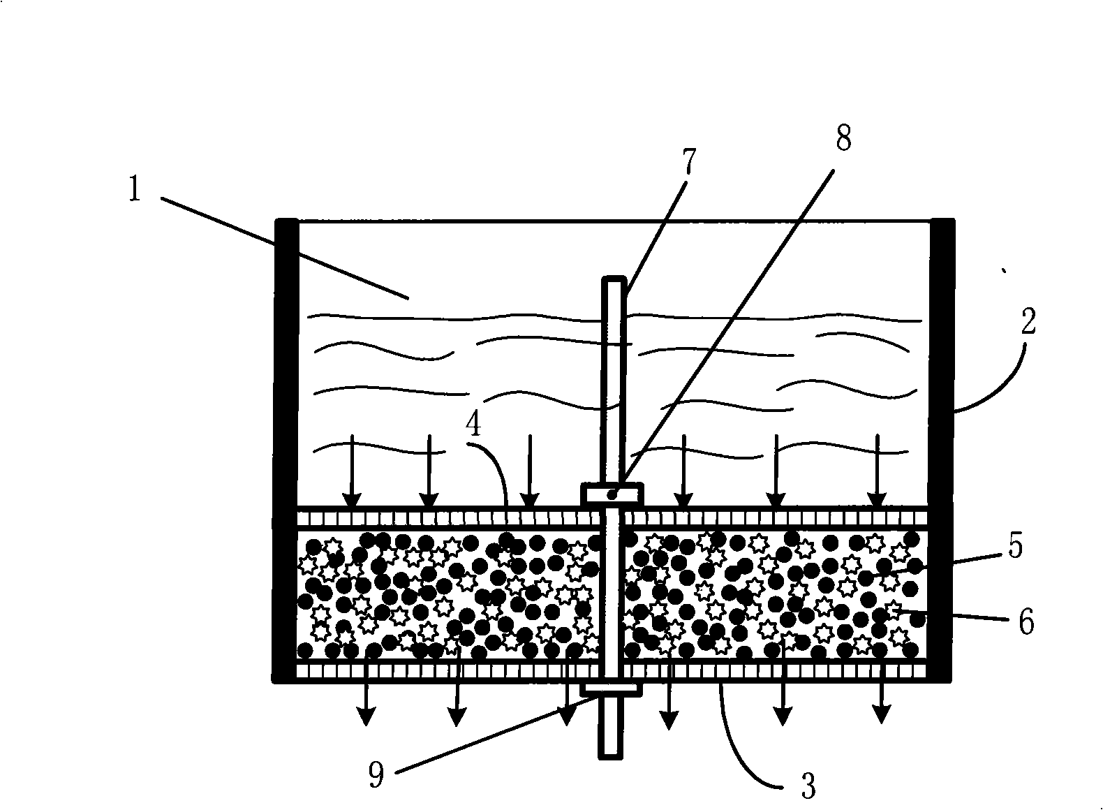
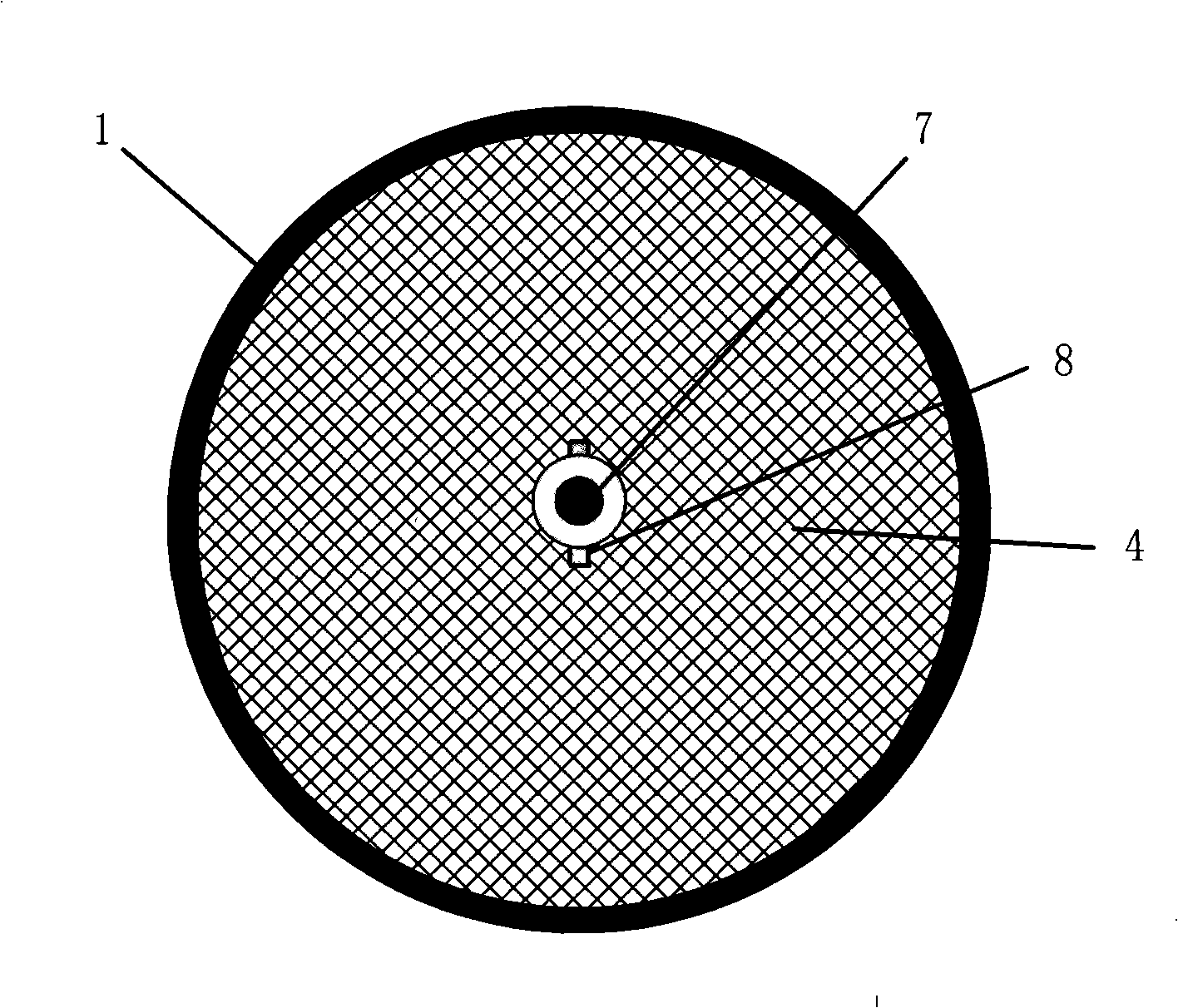
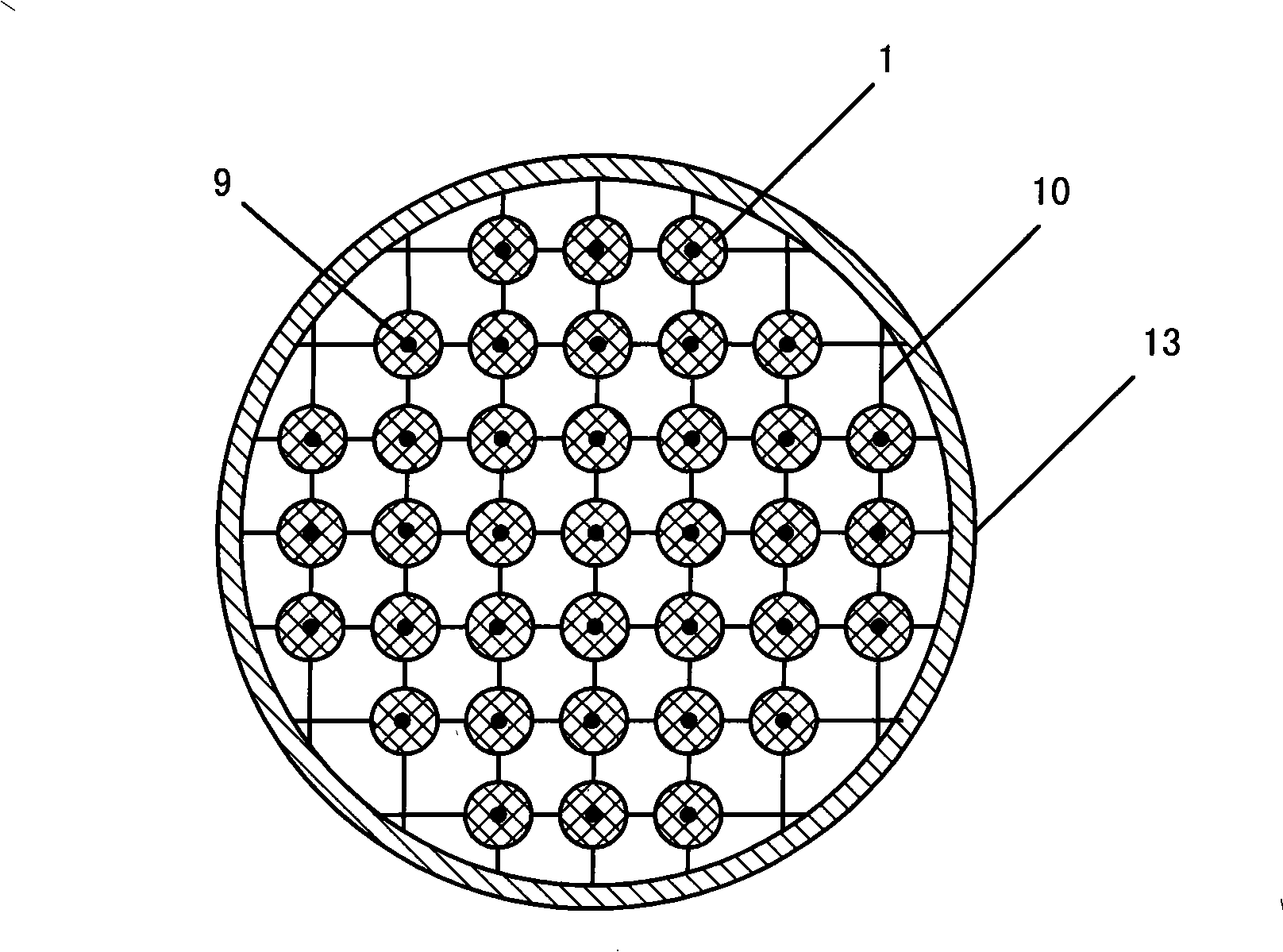
[0030] The catalytic distillation column internals 1 with the efficient mass transfer of circular cross-section are used for the catalytic distillation distillation unit of synthesizing methyl tert-butyl ether (MTBE), the longitudinal section structure of the column internals is as shown in Figure 1, and in the column The cross-section of the part is shown in Figure 2, and the tower internals are fixed at each cross point of the grid support 10 by nuts 9. The arrangement is as shown in Figure 3, and the adjacent upper and lower floors of the tower internals are arranged in a staggered manner. The grid support is fixed on the catalytic distillation tower wall 13, and the total cross-sectional area of ​​the catalytic distillation tower internals on each layer of support is 70% of the catalytic distillation tower cross-sectional area, and stainless steel wire mesh structured packing is arranged below every two layers of tower internals 11. Its height is 20mm. As shown in Figure 5,...

Embodiment 2

[0032] The catalytic distillation column internals 1 of efficient mass transfer with rectangular cross-section is used for the catalytic distillation unit of synthetic ethyl tert-butyl ether (ETBE), the vertical section structure of column internals is as shown in Figure 1, each column At least two parts are fixed on the grid support 10 with nuts 9, and its arrangement is as shown in Figure 4. The total cross-sectional area of ​​the catalytic distillation tower internals on each layer of support is 90% of the catalytic distillation tower cross-sectional area. The grid support is fixed on the catalytic distillation tower wall 13, the upper and lower tower internals are coaxially aligned, and the stainless steel wire mesh structured packing 11 is arranged between the upper and lower tower internals, and its height is 200mm. A liquid distributor 12 is arranged above, as shown in Figure 5, the height of the side wall 2 of the tower internals is 200mm, the opening ratio of the lower...

Embodiment 3

[0034] The catalytic distillation column internals 1 with the efficient mass transfer of rectangular cross section are used for the catalytic distillation unit of synthesizing methyl tert-butyl ether (MTBE), the vertical section structure of column internals is as shown in Figure 1, each column At least two parts are fixed on the grid support 10 with nuts 9, and its arrangement is as shown in Figure 4. The total cross-sectional area of ​​the catalytic distillation tower internals on each layer of support is 95% of the catalytic distillation tower cross-sectional area. The lattice support is fixed on the catalytic distillation tower wall 13, and each adjacent upper and lower two-layer tower internals are arranged in a staggered manner, and a liquid distributor 12 is arranged above each layer of tower internals, such as Figure 7As shown, the height of the side wall 2 of the tower internals is 500mm, the opening ratio of the lower bottom 3 and the upper bottom 4 is 20%, and the ca...


PUM


Abstract

The invention relates to an internal part of a high efficient mass transfer catalytic distillation tower. Wherein, the internal part 1 is composed of a porous container and a filler 5 with catalytic performance therein, the side wall and the lower bottom surface of the container are fixed, at least one longitudinal sliding bar 7 is arranged at the middle part of the lower bottom surface, the upper bottom surface can move up and down along the longitudinal sliding bar and be fixed at an arbitrary height of the sliding bar by a bolt 8, the side wall 2 of the container is not transparent, the upper bottom surface 4 and the lower bottom surface 3 of the container are wire screen plates or porous plates, the internal part is fixed on a grid-shaped support 10 by a nut 9, and the grid-shaped support is fixed on the wall 13 of the catalytic distillation tower. The height of the upper bottom surface of the internal part of the catalytic distillation tower of the invention is lower than the side wall, thereby accumulating liquid with a certain height above a catalyst; reactants are promoted to enter a catalyst bed with the help of the gravity of the liquid, thereby allowing the reactants to be fully contacted with the surface of the catalyst; products are simultaneously impelled to be moved out of the catalyst bed, thereby avoiding the excessive reaction and effectively controlling the retention time of the reactants on the surface of the catalyst.

Description

technical field [0001] The invention relates to an internal part of a catalytic distillation tower with high-efficiency mass transfer, and belongs to the technical field of chemical equipment. Background technique [0002] Catalytic distillation tower is a kind of chemical equipment with both reaction function and separation function. The internal components in the reaction zone must have the dual functions of catalysis and vapor-liquid contact mass transfer. This kind of column internals is also called catalytic distillation. The structural performance of the tower packing directly affects the efficiency of the catalytic distillation process. It is necessary to keep the vapor-liquid two-phase in the reaction zone in full contact and to make the contact time between the reactants and the solid catalyst easy to control. However, the current catalytic distillation tower packing structure is still This requirement cannot be met. [0003] Patents and literature reports on the p...

Claims


Application Information

Patent Timeline
Patent Type & Authority Applications(China)
IPC IPC(8): B01D3/00B01J8/02B01J19/30
Inventor 李永红广翠李鑫钢李洪高鑫
Owner TIANJIN UNIV
Why Eureka
Try Eureka