

Delayed coker isolation valve systems
A technology of isolation system and isolation valve, which is used in coking carbonaceous materials, coke ovens, valve devices, etc., can solve problems such as inoperability, and achieve the effect of preventing accumulation and reliable use.
- Summary
- Abstract
- Description
- Claims
- Application Information
AI Technical Summary
Problems solved by technology
Method used
Image

Examples
Embodiment Construction
[0024] It will be readily appreciated that the components of the invention, as generally illustrated and shown in the figures herein, may be arranged and designed in a wide variety of different configurations. Accordingly, the following more detailed description of embodiments of the system, apparatus, and method of the present invention, as represented in Figures 1 to 8, is not intended to limit the scope of the invention as claimed, but only representative of some examples.
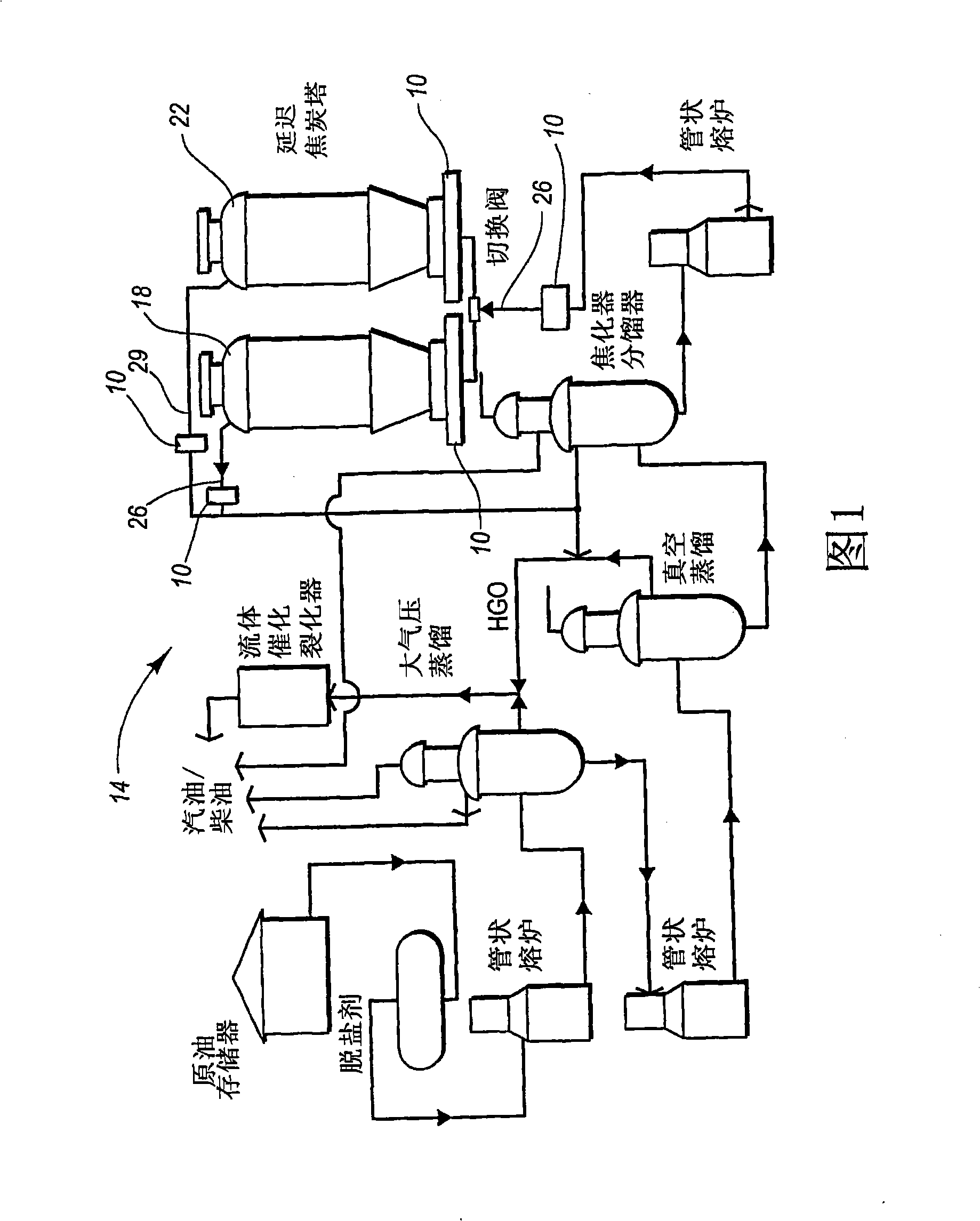
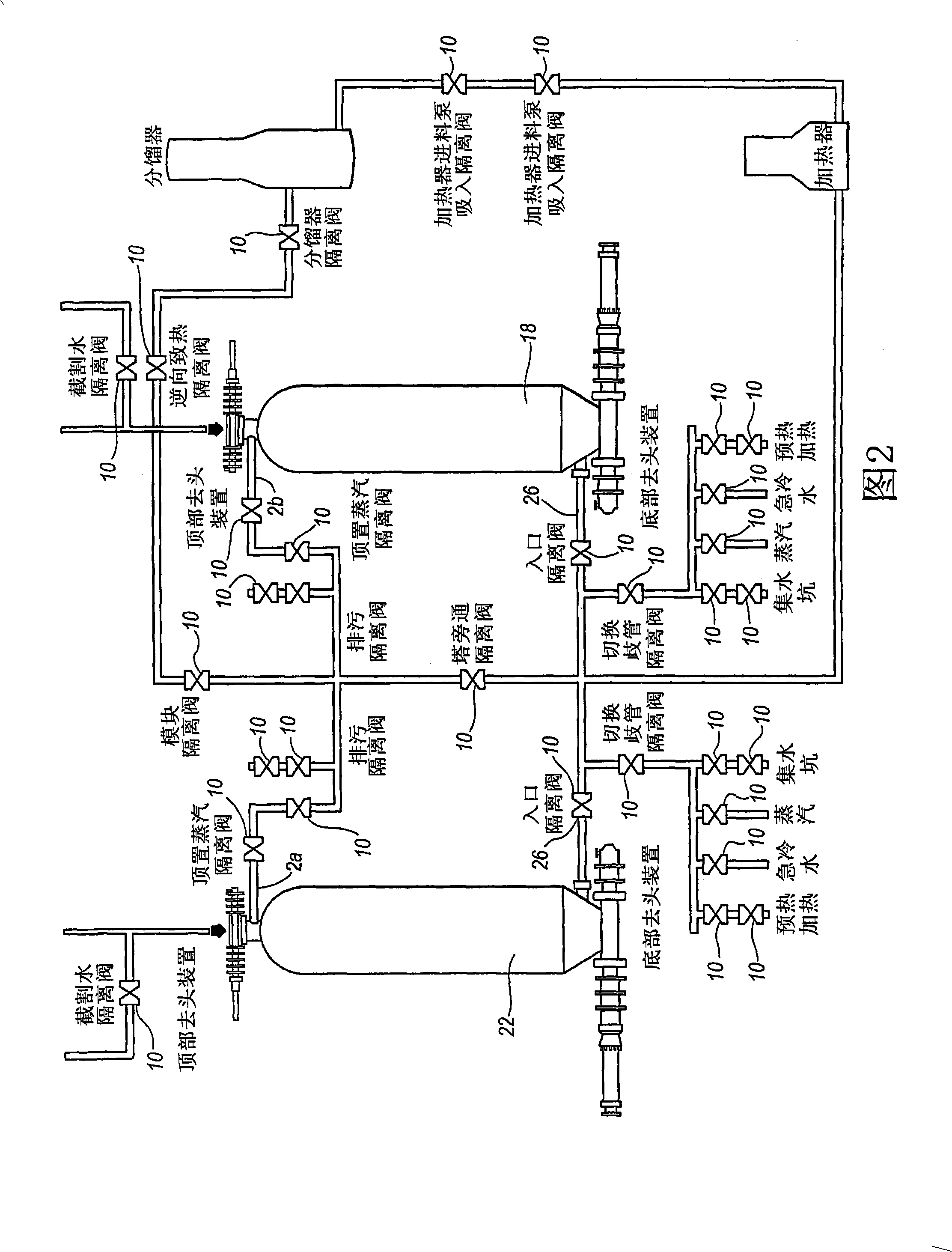
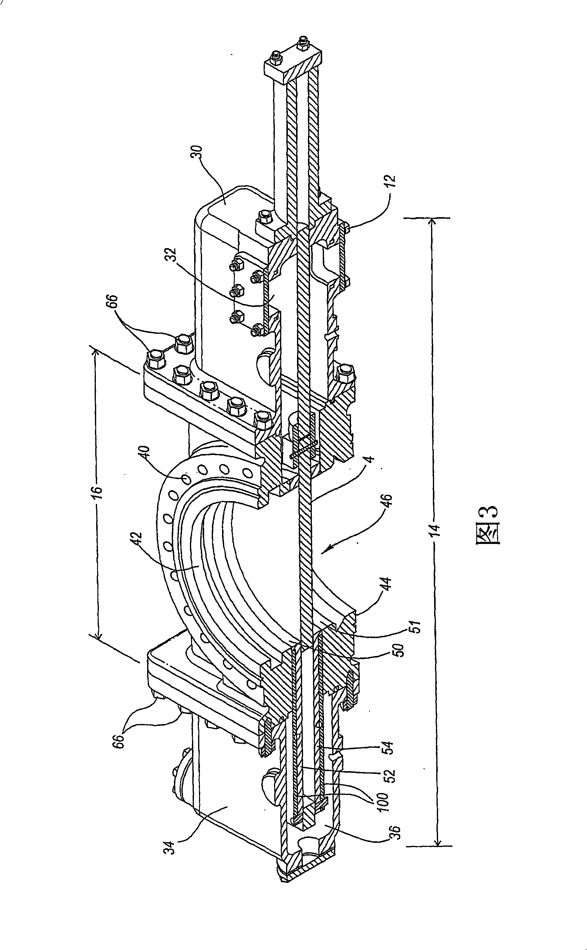
[0025] Embodiments of the present invention may be better understood with reference to the drawings, wherein like parts are designated like numerals throughout. While reference is made to the drawings and corresponding discussion below, the following detailed description is divided into several sections. The first part pertains to and presents an overview of the delayed coking process. The second section pertains to and sets forth isolation valve systems including various valves or valve formats that ...
PUM
 Abstract
Description
Claims
Application Information