Firing jig and method for manufacturing honeycomb structured body

A technology for a honeycomb structure and a manufacturing method, which can be applied in applications, household appliances, ceramic products, etc., can solve problems such as increased operating costs and coating peeling, and achieve the effects of reducing operating costs and preventing unstable firing conditions.

Inactive Publication Date: 2008-12-10
IBIDEN CO LTD
View PDF1 Cites 1 Cited by
  • Summary
  • Abstract
  • Description
  • Claims
  • Application Information

AI Technical Summary

Problems solved by technology

[0012] However, when the firing jig of Patent Document 1 is used, although the sintering of the silicon carbide particles is promoted, peeling of the coating layer may occur on the mounting surface of the formed honeycomb body during the repetition of the firing process.
In the case of peeling of the coating, it can no longer be used as a firing rack, so it needs to be replaced with a new firing rack, which leads to an increase in operating costs

Method used


Image

  • Firing jig and method for manufacturing honeycomb structured body
  • Firing jig and method for manufacturing honeycomb structured body
  • Firing jig and method for manufacturing honeycomb structured body

Examples


no. 1 approach

[0061] Next, a first embodiment, which is one embodiment of the present invention, will be described with reference to the drawings.

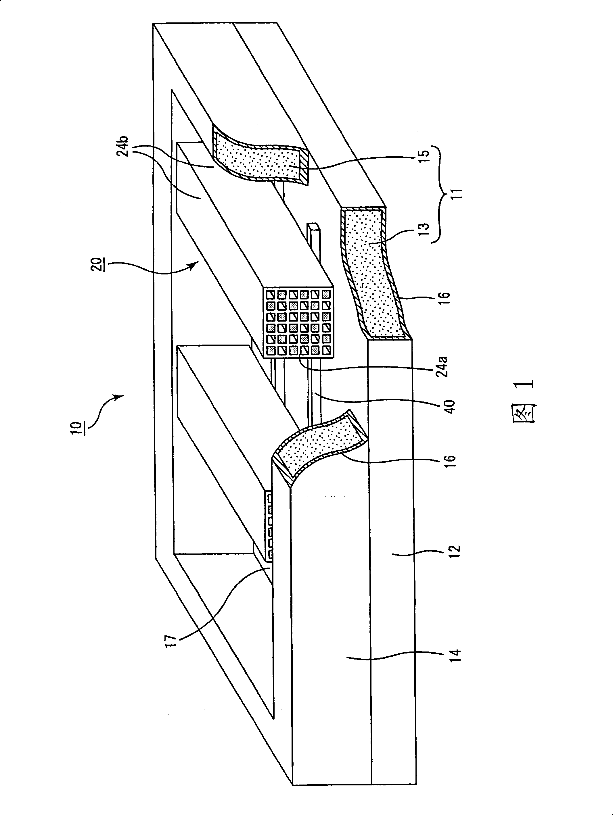
[0062] Fig. 1 is a partially cutaway perspective view schematically showing a firing jig according to a first embodiment of the present invention.

[0063] The firing rack 10 is composed of a bottom plate 12 and a frame material 14, and the frame material 14 is placed on the bottom plate 12 so that both are integrated. The frame material 14 is fixed to the base plate 12 by fitting the protrusions formed on the lower surface of the frame material 14 and the recesses formed on the upper surface of the base plate 12 to each other.

[0064] The bottom plate 12 is composed of a carbon base material 13 and a coating layer 16 formed on the surface of the base material 13, and the frame material 14 is composed of a carbon frame base material 15 and a coating layer 16 formed on the surface of the frame base material 15. . In the firing jig 10 shown in...

Embodiment 1

[0105]On the surface of a box-shaped frame with an open upper part made of carbon (DSG-332 manufactured by SEC Co., Ltd.) consisting of a bottom base material and a frame base material, on the mounting surface of the honeycomb formed body of the base base material and the surface of the frame base material On the surface, a dense SiC coating composed of SiC is formed by chemical vapor infiltration (CVI). Place the above-mentioned base material in the reactor, use methyltrichlorosilane as the gas phase raw material, let the gas phase raw material flow into the reactor with a temperature of 1500°C and reduce the pressure, and precipitate SiC with a thickness of about 90 μm, thereby performing SiC Coating formation. Precipitation of SiC is performed once.

Embodiment 2

[0107] 60 g of silicon carbide powder, 3 g of tetrabutoxytitanium, 17 g of silicone resin, and 20 g of xylene were kneaded to prepare a SiC layer forming material. On the surface of a box-shaped frame with an open upper part made of carbon (DSG-332 manufactured by SEC Co., Ltd.) consisting of a bottom base material and a frame base material, on the mounting surface of the honeycomb formed body of the base base material and the surface of the frame base material On top, the SiC coating material (spray weight: 25 g) was sprayed with a spray gun, and dried at 80° C. for 20 minutes and at 230° C. for 20 minutes using a dryer, thereby forming a SiC coating on the surface of the frame.


PUM

PropertyMeasurementUnit
heightaaaaaaaaaa
surface roughnessaaaaaaaaaa
thicknessaaaaaaaaaa

Abstract

Provided is a manufacturing method for a jig for firing and a honeycomb structural body. The jig for firing that even when repeatedly used in the firing of honeycomb molding while satisfactorily advancing the reaction of sintered body generation, is capable of preventing any coat layer detachment and is employable over a prolonged period of time to thereby attain reduction of running cost. The jig for firing is a jig for honeycomb molding firing including a housing for mounting thereon a columnar honeycomb molding composed mainly of silicon carbide with its side face laid down and including a coat layer provided on at least a face for honeycomb molding mounting of the housing, characterized in that the coat layer is composed mainly of silicon carbide, and that the arithmetic mean height of the coat layer determined in accordance with JIS B 0601(2001) is 10 mum or less.

Description

technical field [0001] The present invention relates to a firing frame and a method for manufacturing a honeycomb structure. Background technique [0002] Recently, it has become a problem that particulates contained in exhaust gas exhausted from internal combustion engines of vehicles such as buses and trucks and construction machinery cause damage to the environment and human bodies. [0003] Various ceramic filters have been proposed, which are filters for purifying the exhaust gas by trapping particles in the exhaust gas by passing the exhaust gas through porous ceramics. [0004] In the ceramic filter, for example, two or more fired honeycomb bodies which are porous ceramic bodies are bundled with a sealing material layer interposed therebetween, and a sealing material layer is formed around it. In addition, in this honeycomb fired body, many through-holes are formed in the longitudinal direction, and the through-hole walls that separate these through-holes function as...

Claims


Application Information

Patent Timeline
Patent Type & Authority Applications(China)
IPC IPC(8): C04B35/64C04B41/85C04B35/66C04B38/00
CPCC04B41/5059C04B41/009C04B41/87F27D5/0031Y10T428/1317
Inventor 西城贵满
Owner IBIDEN CO LTD
Why Eureka
Try Eureka