
Mine gas beam tube monitoring system and recognition method for gas explosivity and fire danger

A beam tube monitoring and gas technology, applied in mining equipment, mining equipment, fuel oil testing, etc., can solve the problems of inability to judge the fire hazard system and poor real-time performance, and achieve the effects of convenient expansion, long service life and low cost

Active Publication Date: 2008-12-10
CCTEG SHENYANG RES INST
View PDF0 Cites 32 Cited by
  • Summary
  • Abstract
  • Description
  • Claims
  • Application Information

AI Technical Summary

Problems solved by technology

[0065]At present, the above fire hazard identification methods are generally used alone, and cannot make a systematic judgment on the fire hazard, and at the same time, the real-time performance is poor

Method used


Image

  • Mine gas beam tube monitoring system and recognition method for gas explosivity and fire danger
  • Mine gas beam tube monitoring system and recognition method for gas explosivity and fire danger
  • Mine gas beam tube monitoring system and recognition method for gas explosivity and fire danger

Examples


no. 1 example

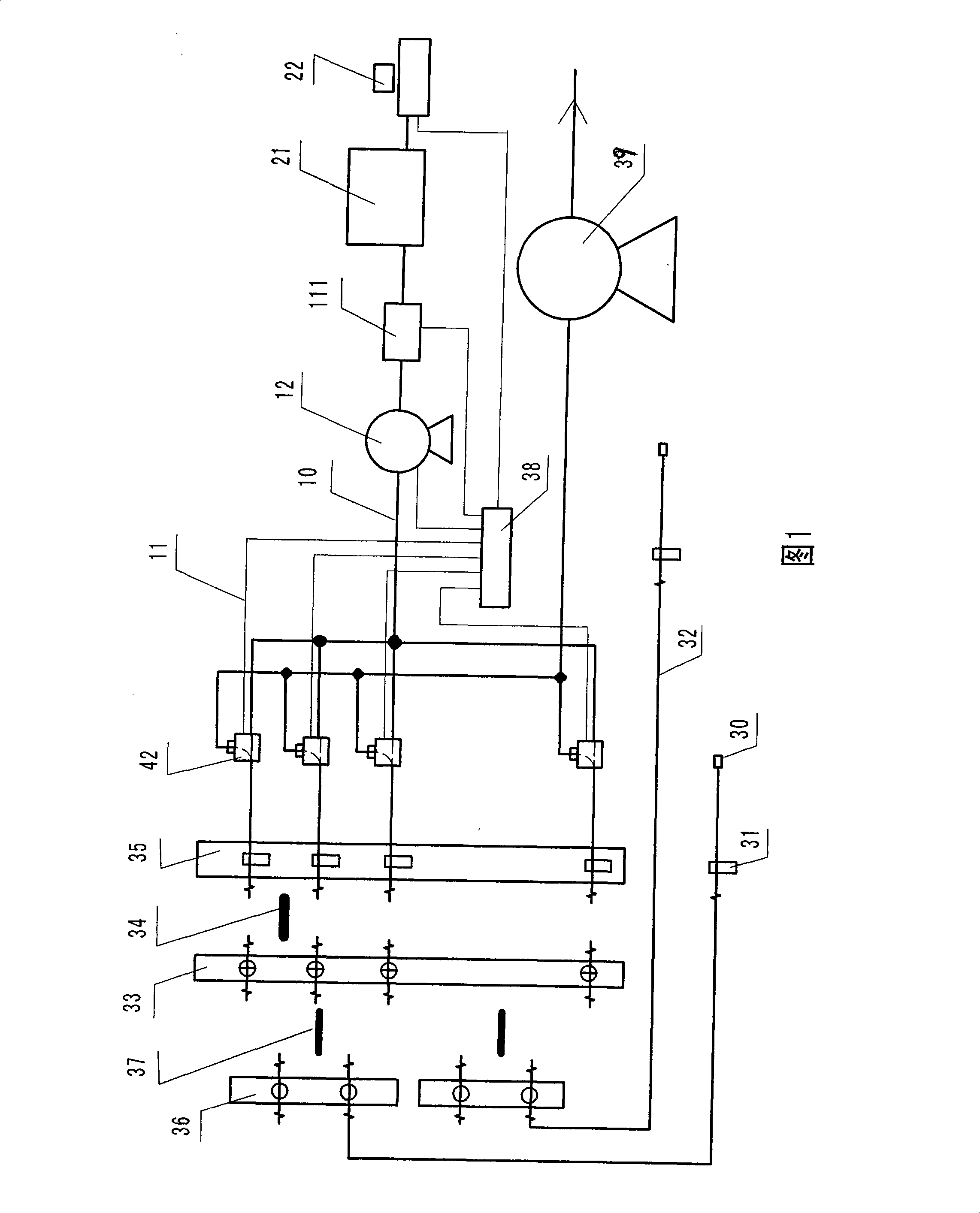
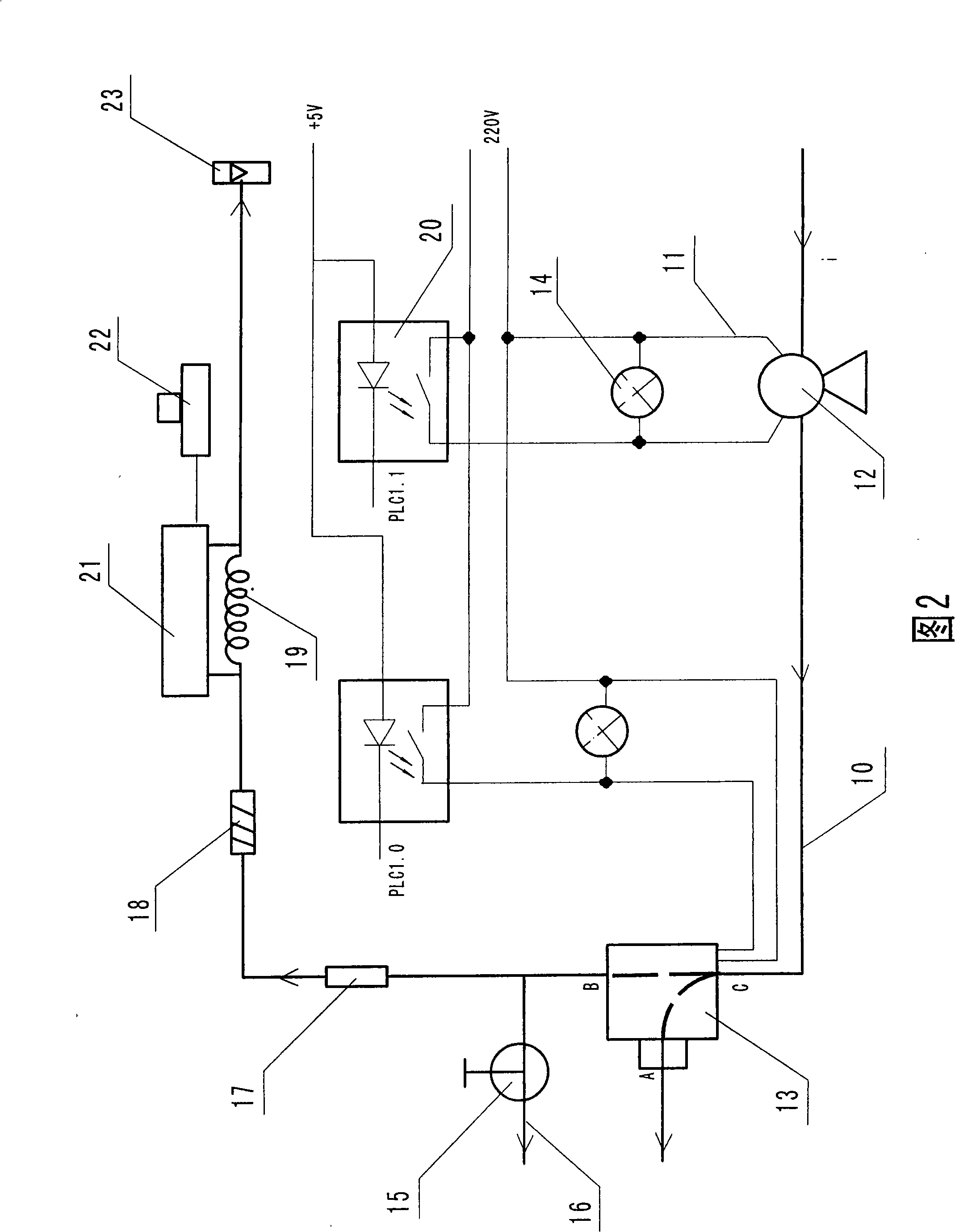
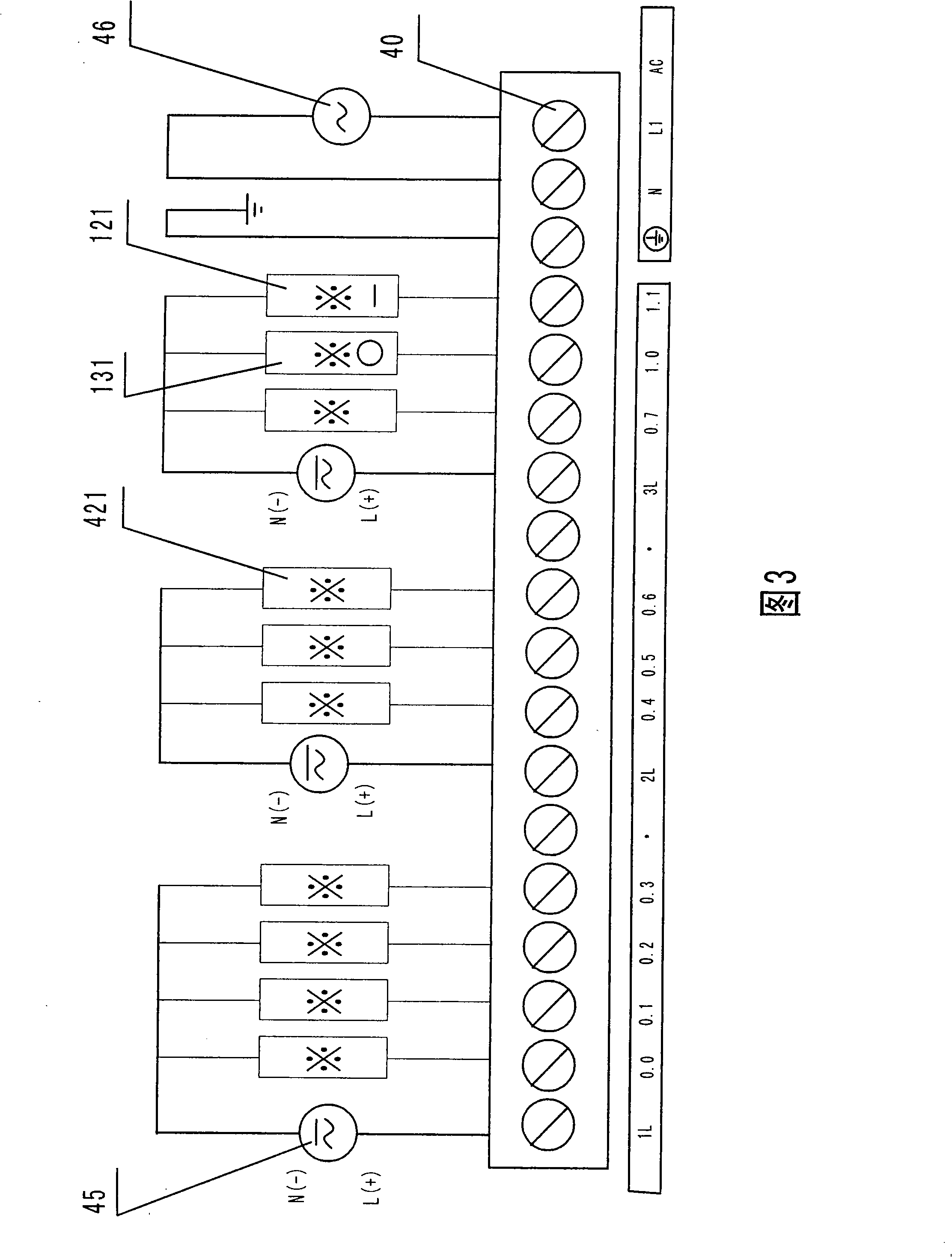
[0121] The first embodiment, referring to Fig. 1, Fig. 2, Fig. 3, Fig. 4, a kind of mine gas bundle tube monitoring system, it comprises the single-way gas-water separator 31 that is provided with the middle of several end fixed samplers 30 The core tube 32 is connected to the branch box 36, and then connected to the connection box 33 through the branch tube cable 37, and the main tube cable 34 composed of several single-core tubes from the connection box 33 is connected to the gas-water separator box 35 Afterwards, the automatic sampling device is composed of the gas circuit switching solenoid valve 42 and the air pump 39 controlled by the programmable controller-PLC38 through the electrical control circuit 11, which is characterized in that it is also controlled by the automatic sampling pipeline 10 sequentially connected to the programmable controller The oil-free gas injection pump 12, switching solenoid valve 13, diverting needle valve 15 with venting end 16, dryer 17, fil...

no. 2 example

[0123] The second embodiment, referring to Fig. 1, Fig. 2, Fig. 3, Fig. 4, a kind of mine gas beam tube monitoring system, it comprises the single-way gas-water separator 31 that is provided with the middle of several end fixed samplers 30 The core tube 32 is connected to the branch box 36, and then connected to the connection box 33 through the branch tube cable 37, and the main tube cable 34 composed of several single-core tubes from the connection box 33 is connected to the gas-water separator box 35 Afterwards, the automatic sampling device is composed of the gas circuit switching solenoid valve 42 and the air pump 39 controlled by the programmable controller-PLC38 through the electrical control circuit 11, which is characterized in that it is also controlled by the automatic sampling pipeline 10 sequentially connected to the programmable controller The oil-free gas injection pump 12, switching solenoid valve 13, diverting needle valve 15 with venting end 16, dryer 17, filt...

no. 3 example

[0129] The third embodiment, see Fig. 6, Figure 8 , Fig. 1, a gas explosiveness identification method, including the explosion triangle method (X 1 , Y 1 ) is the L coordinate of the 100% lower limit point, (X u , Yu ) is the U coordinate of the 100% upper limit point, (X S , Y S ) is the S coordinate of the 100% critical point, which is characterized by (X 1 50,Y 1 50) is the 50% lower limit point L 50 Coordinates, (X u 50,Y u 50) is the 50% upper limit point U 50 Coordinates, (X S 50,Y S 50) is the 50% critical point S 50 Coordinates, (X 1 75,Y 1 75) is the 75% lower limit point L 75 Coordinates, (X u 75,Y u 75) is the 75% upper limit point U 75 Coordinates, (X S 75,Y S 75) is the 75% critical point S 75 coordinate,

[0130] x 1 50=X 1 / 2,Y 1 50=(20.93-Y 1 ) / 2+Y 1

[0131] x u 50=(100-X u ) / 2+X u , Y u 50=Y u / 2

[0132] x S 50=X S / 2,Y S 50=Y S / 2

[0133] x 1 75=X 1 50+X 1 50 / 2, Y 1 75=(20.93-Y 1 50)-Y 1 50 / 2

[0134] x u 75=(1...


PUM


Abstract

The invention relates to a mine gas beam tube monitoring system, comprising an automatic sampling device which consists of a gas path switching electromagnetic valve and a suction pump. The gas path switching electromagnetic valve is connected with a partial channel through a sampler and a single-core beam tube of a moisture separator and then a conduit head through a partial beam tube cable and is controlled by a programmable controller after a main beam tube cable is connected with a moisture separator box. The system is characterized in that the monitoring system also comprises an automatic sampling device which is composed of a sample making device. The sample making device consists of a non-oil injection pump and a conversion electromagnetic valve controlled by the programmable controller, a shunting needle-shaped valve with an emptying end, a dryer, a filtering device, a quantitative tube and a single-core beam tube of a flow meter which are successively connected through an automatically sampling pipe. The automatic sampling device is connected with a gas chromatography detection device for analyzing and outputting data to a computer. The computer controls the programmable controller and outputs detection results. The dryer and the filtering device are provided with long service life. The measuring point number extension is convenient and can be maintained easily. The cost is low. The sampling device samples steadily. The precision of detected gas is high. A recognition method for the gas explosiveness and the fire hazard is disclosed. The decision according to the analysis result is clear and prompt.

Description

Technical field [0001] The invention belongs to the field of mine gas composition monitoring and gas explosiveness and fire hazard identification methods, including the field of gas composition monitoring and gas explosiveness and fire hazard identification methods in tunnels, natural gas, and oil exploitation, and particularly relates to a coal mine underground gas bundle tube monitoring system and Identification method of mine combustible gas explosiveness and fire hazard degree. Background technique [0002] At present, the mine gas bundle tube monitoring system has begun to be popularized and applied in coal mines. The mine gas bundle tube monitoring system is to use the bundle tube to extract the gas from each measuring point in the mine under negative pressure through the air pump and collect it to the designated place, and then analyze the underground gas samples collected by the bundle tube with the help of a gas chromatography detection device to realize CO, CO 2 ...

Claims


Application Information

Patent Timeline
Patent Type & Authority Applications(China)
IPC IPC(8): G01N30/02G01N1/24G01N30/24E21F17/18G06F19/00G01N33/22
Inventor 王理
Owner CCTEG SHENYANG RES INST
Learn More