Debugging method of cavity band-pass filter

A technology of band-pass filter and debugging method, which is applied in the direction of waveguide devices, instruments, measuring devices, etc., can solve the problems of long time, long debugging time, and relatively high professional requirements for debugging personnel, and achieve fast speed and professional requirements Low, good consistency

Inactive Publication Date: 2008-12-10
ANHUI TATFOOK TECH CO LTD
View PDF0 Cites 8 Cited by
  • Summary
  • Abstract
  • Description
  • Claims
  • Application Information

AI Technical Summary

Problems solved by technology

[0006] First, it takes a long time to debug. Directly observe the in-band loss and out-of-band suppression. All the debugging screws usually need to go through many rounds to debug the filter, which takes a long time.
[0007] The second is that the professional requirements for debugging personnel are relatively high. Due to the adjustment of any resonant screw or coupling, the in-band return loss and out-of-band rejection of the filter will change. There is a lot of blindness in debugging, and only very professional After a period of training, the debugging personnel can judge the depth of some key screws and quickly debug the filter
[0008] The third is that the batch consistency cannot be guaranteed. During mass production, a small number of products have the effects of production and processing errors, poor assembly and welding, etc., resulting in the failure of the filter to be successfully debugged, or even if the in-band return loss and out-of-band suppression parameters are successfully debugged, the debugging screw Compared with other products, the depth of the filter varies greatly, which in turn affects the power capacity and other performance of the cavity filter

Method used


Image

  • Debugging method of cavity band-pass filter

Examples


Embodiment Construction

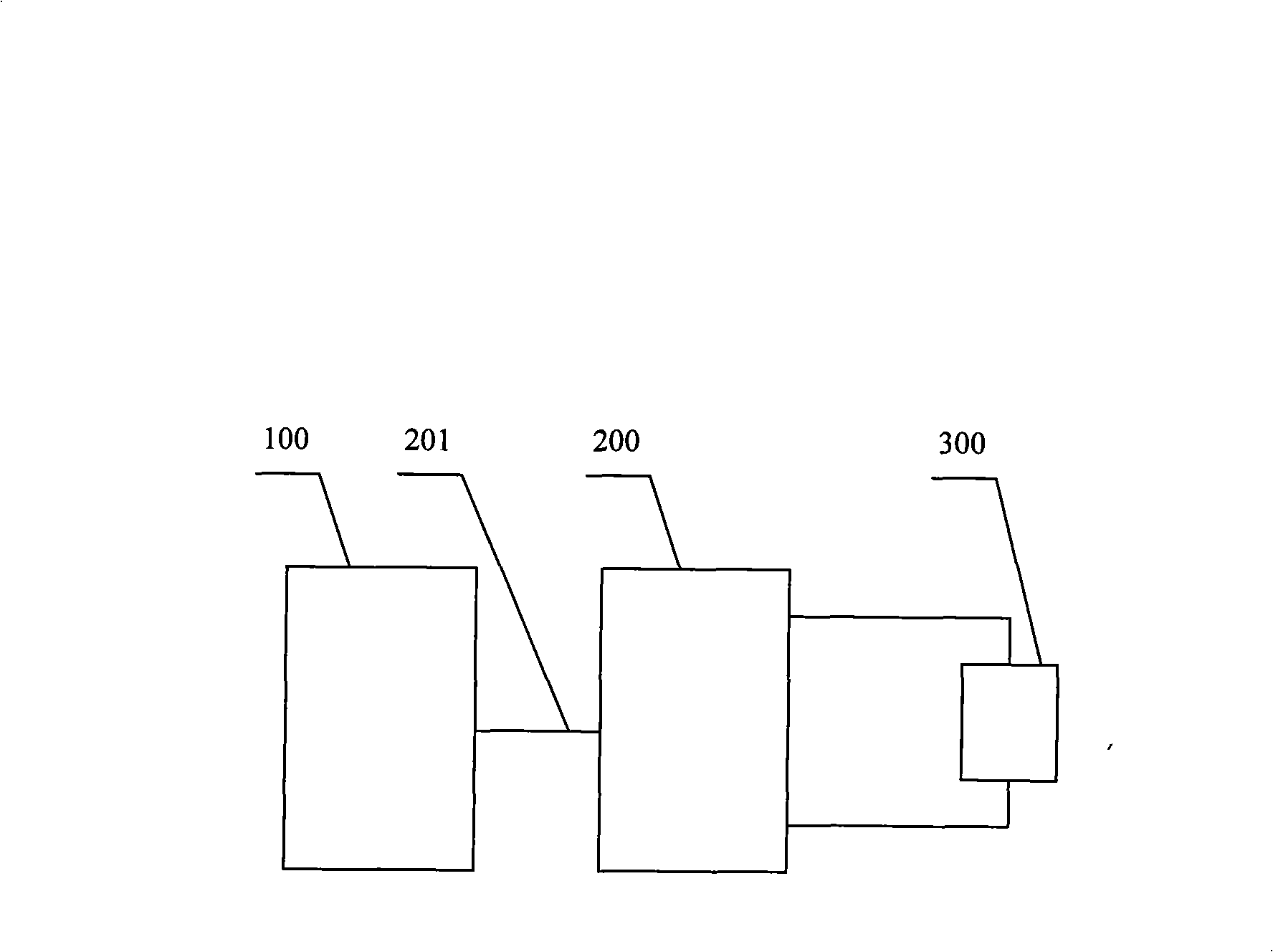
[0019] In a preferred embodiment of the present invention, first extract the standard model parameters such as the resonant frequency and the coupling coefficient of the cavity bandpass filter, that is, select a cavity bandpass filter with the best performance index that has been debugged as the standard cavity bulk filter. The vector network analyzer 200 is connected to the standard cavity filter 300 , and one end of the communication line 201 is connected to the PC 100 , and the other end is connected to the vector network analyzer 200 . Run the debugging software in the PC 100 and perform the test. The PC 100 reads the test data of the vector network analyzer 200, and converts them into parameters such as the cavity resonant frequency and coupling coefficient of the filter through calculation. This set of data is used as The parameters of the standard model model of the filter to be tested are prestored in the PC 100 . Modeling is carried out through a large amount of test...


PUM


Abstract

This invention related to a method for modulating cavity band-pass filter, belonging to the technical field of micro-wave passive filter, especially belonging to use a vector network analyzer to modulate in-band return loss and out-band restraint of the cavity band-pass filter. The method for modulating cavity band-pass filter of this invention is to solve problems that the method for using the vector network analyzer to modulate in-band return loss and out-band restraint of the cavity band-pass filter is slow and the batch consistency is bad and the human factor affects the quality, including: using one end of a communication line to connect to a PC machine as well as the other connect to the vector network analyzer whose two ports are respectively connected to the cavity band-pass filter to be modulated, adjusting a bolt to an expected position based on a deviated position indication of a bolt displayed at a modulating software interface of the PC machine. This modulating method has quick speed, good batch consistency, small human factor, and is suitable for analyzing the vector network and modulating the cavity band-pass filter, the duplexer and the multiplexer.

Description

technical field [0001] The present invention relates to a debugging method of a cavity bandpass filter, which belongs to the technical field of microwave passive filters, and in particular belongs to using a vector network analyzer to debug the in-band return loss and out-of-band of a cavity bandpass filter inhibition. Background technique [0002] Cavity bandpass filters are widely used in communication systems. In order not to affect the performance of communication systems, the requirements for in-band loss and out-of-band suppression of cavity bandpass filters are particularly high, and then the resonant frequency of the filter The error requirements of parameters such as coupling coefficient and coupling coefficient are very high. The in-band loss and out-of-band rejection of cavity bandpass filters are usually measured with a vector network analyzer. [0003] There are many debugging screws on the cavity bandpass filter. The debugging screws are divided into resonant...

Claims


Application Information

Patent Timeline
Patent Type & Authority Applications(China)
IPC IPC(8): H01P1/207H01P1/20G01R27/28
Inventor 孙尚传李锋徐斐陈家林
Owner ANHUI TATFOOK TECH CO LTD
Why Eureka
Try Eureka