
Micro-miniature terminal antenna based on composite right/left-handed transmission line

A technology that combines left and right hand and terminal antennas, applied in slot antennas, radiating element structures, circuits, etc., can solve the problems of small bandwidth and difficult to meet, and achieve the effect of reducing size

Inactive Publication Date: 2008-12-10
上海联能科技有限公司
View PDF0 Cites 8 Cited by
  • Summary
  • Abstract
  • Description
  • Claims
  • Application Information

AI Technical Summary

Problems solved by technology

[0003] Itoh et al. introduced an antenna design method based on composite left-handed transmission line technology in the literature and related literature. The geometric size of the antenna designed by this method can be reduced to less than one-twentieth of the wavelength. The fly in the ointment is that this Sievenpiper Antennas designed with a mushroom structure have a very small bandwidth (usually less than 1%), which is difficult to meet the requirements of most practical applications

Method used


Image

  • Micro-miniature terminal antenna based on composite right/left-handed transmission line
  • Micro-miniature terminal antenna based on composite right/left-handed transmission line
  • Micro-miniature terminal antenna based on composite right/left-handed transmission line

Examples


Embodiment 1

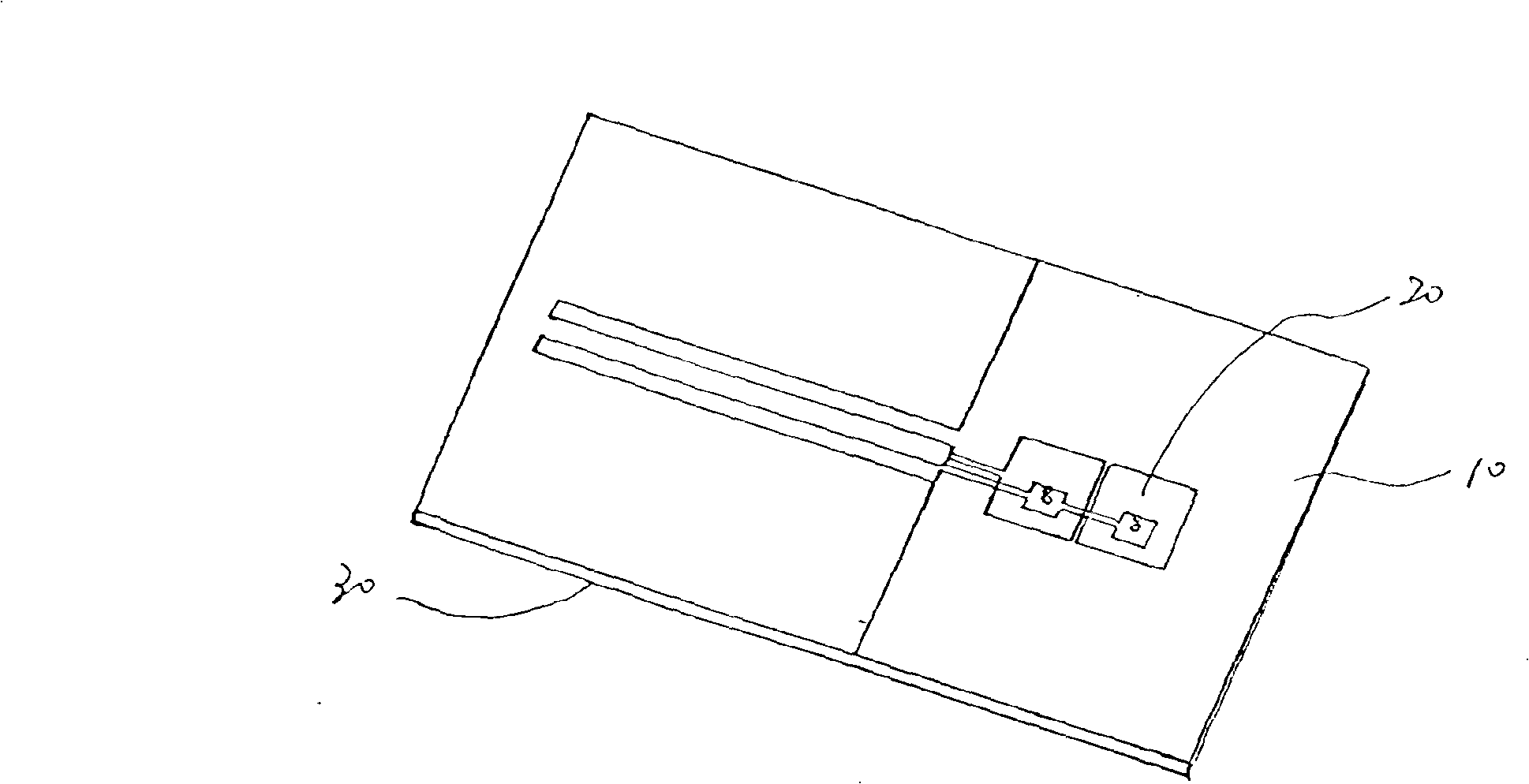
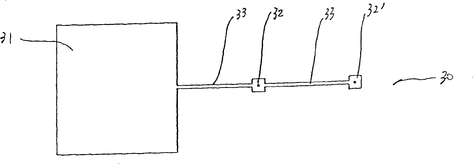
[0046] see figure 1 is a schematic structural diagram of an ultra-small terminal antenna in Embodiment 1 of the present invention, figure 2 It is a schematic diagram of the upper surface element structure of the ultra-small terminal antenna in Embodiment 1 of the present invention and image 3 As shown in the schematic diagram of the structure of the lower surface element of the ultra-small terminal antenna in Embodiment 1 of the present invention, an ultra-small terminal antenna based on a composite left-handed transmission line includes a microwave dielectric substrate 10 covered with copper foil. The upper surface element 20 and the lower surface element 30 formed on the upper and lower surfaces of the dielectric substrate, wherein,

[0047] The upper surface element 20 includes an upper floor 21, a coplanar waveguide feeder 22 and two upper radiation patches 23, 23', a groove 40 is etched between the upper floor 21 and the coplanar waveguide feeder 22, and the coplanar w...

Embodiment 2

[0053] see Figure 4 It is a schematic diagram of the upper surface element structure of the ultra-small terminal antenna in Embodiment 2 of the present invention and Figure 5 As shown in the schematic diagram of the lower surface element structure of the ultra-small terminal antenna in Embodiment 2 of the present invention, an ultra-small terminal antenna based on a composite left-handed transmission line includes a copper-clad microwave dielectric substrate 10 (not shown in the figure). The upper surface element 20 and the lower surface element 30 formed on the microwave dielectric substrate and the lower surface by etching copper foil, wherein,

[0054] The upper surface element 20 includes an upper floor 21, a coplanar waveguide feeder 22, an upper radiation patch 23, an upper connection line 24, and a connecting piece 25 at the front end of the upper connection line 24, between the upper floor 21 and the coplanar waveguide feeder 22 Grooves 40 are etched, the coplanar w...

Embodiment 3

[0059] see Figure 7 It is a schematic diagram of the upper surface element structure of the ultra-small terminal antenna in Embodiment 3 of the present invention and Figure 8 As shown in the schematic diagram of the structure of the lower surface element of the ultra-small terminal antenna in Embodiment 3 of the present invention, an ultra-small terminal antenna based on a composite left-handed transmission line includes a copper-clad microwave dielectric substrate 10, and the copper foil is etched on the microwave The upper surface element 20 and the lower surface element 30 formed on the upper and lower surfaces of the dielectric substrate, wherein,

[0060] The upper surface element 20 includes an upper floor 21, a coplanar waveguide feeder 22, an upper radiation patch 23, an upper connection line 24, and a connecting piece 25 at the front end of the upper connection line 24, between the upper floor 21 and the coplanar waveguide feeder 22 Grooves 40 are etched, the copla...


PUM


Abstract

The invention provides a composite left and right hand transmission wire-based ultra small terminal antenna, comprising a copper clad microwave dielectric substrate, components formed on upper and lower surfaces of the microwave dielectric substrate trough etching copper foil; wherein, the microwave dielectric substrate is composite left and right hand material; the upper surface component comprises N upper radiating patches, with N as an natural number not less than 1; the lower surface component comprises a lower floor and a small-size lower connecting floor with an area less than that of the upper radiating patch; the lower floor and the small-size lower connecting floor are connected through a lower connecting line; the upper radiating patch is communicated to the small-size lower connecting floor through a shortcut needle; the quantity of the upper radiating patch is identical with that of the small-size lower connecting floor, or the quantities are different. The advantage is as follows: the small-size lower connecting floor connected to the lower floor is applied to replacing the former whole floor in the invention, so as to obtain the ultra small terminal antenna; the upper surface component is provided with the mode of connecting piece further, so as to enhance electromagnetic coupling of the connecting line with the upper radiating patch on coplanar wave guide, so as to enhance operation band width of the antenna.

Description

technical field [0001] The invention relates to an antenna, in particular to an ultra-small mobile terminal antenna based on composite left and right hand transmission line technology. Background technique [0002] Left-handed materials (Left-Handed Metamaterials) is one of the research hotspots in the field of materials science and physics in recent years. When it comes to left-hand materials, we have to start with right-hand materials. In the classical electrodynamic theory, the electromagnetic properties of dielectric materials can be described by two macroscopic parameters, the permittivity ε and the magnetic permeability μ. The ε and μ of matter in nature are both positive numbers. When the electromagnetic wave passes through it, the three physical quantities describing the propagation characteristics of the electromagnetic wave, the electric field direction E, the magnetic field direction H and the propagation direction K of the electromagnetic wave, form a one-to-one...

Claims


Application Information

Patent Timeline
Patent Type & Authority Applications(China)
IPC IPC(8): H01Q1/38H01Q13/10
Inventor 贺连星关放鲍军傅敏礼
Owner 上海联能科技有限公司
Learn More