Method for burning sludge of chain furnace

A technology for incinerating sludge and chain furnace, applied in the combustion method, incinerator, combustion type and other directions, can solve the problems of insufficient heat source, stable furnace temperature interference, boiler steam pressure drop, etc., and achieve easy ignition and incineration, effective heating value The effect of utilizing and improving thermal efficiency

Inactive Publication Date: 2008-12-17
ZHEJIANG HUAZHANG TECH
View PDF0 Cites 9 Cited by
  • Summary
  • Abstract
  • Description
  • Claims
  • Application Information

AI Technical Summary

Problems solved by technology

If the grate speed is reduced according to the sludge combustion characteristics, there will be insufficient heat source, resulting in problems such as unstable furnace temperature and lower boiler steam pressure; if the grate speed is increased, although the normal boiler steam pressure and furnace temperature are guaranteed, it will cause problems Incomplete coal combustion occurs, and black coal particles are mixed in the slag
In addition, the control of the throwing amount of the coal thrower is realized by manually controlling the coal throwing speed or controlling the opening of the coal thrower opening. This rough control method will inevitably interfere with the stability of the furnace temperature and affect Thermal efficiency of chain furnace

Method used


Image

  • Method for burning sludge of chain furnace
  • Method for burning sludge of chain furnace
  • Method for burning sludge of chain furnace

Examples


Embodiment Construction

[0015] The present invention will be further described below by means of embodiments in conjunction with the accompanying drawings.

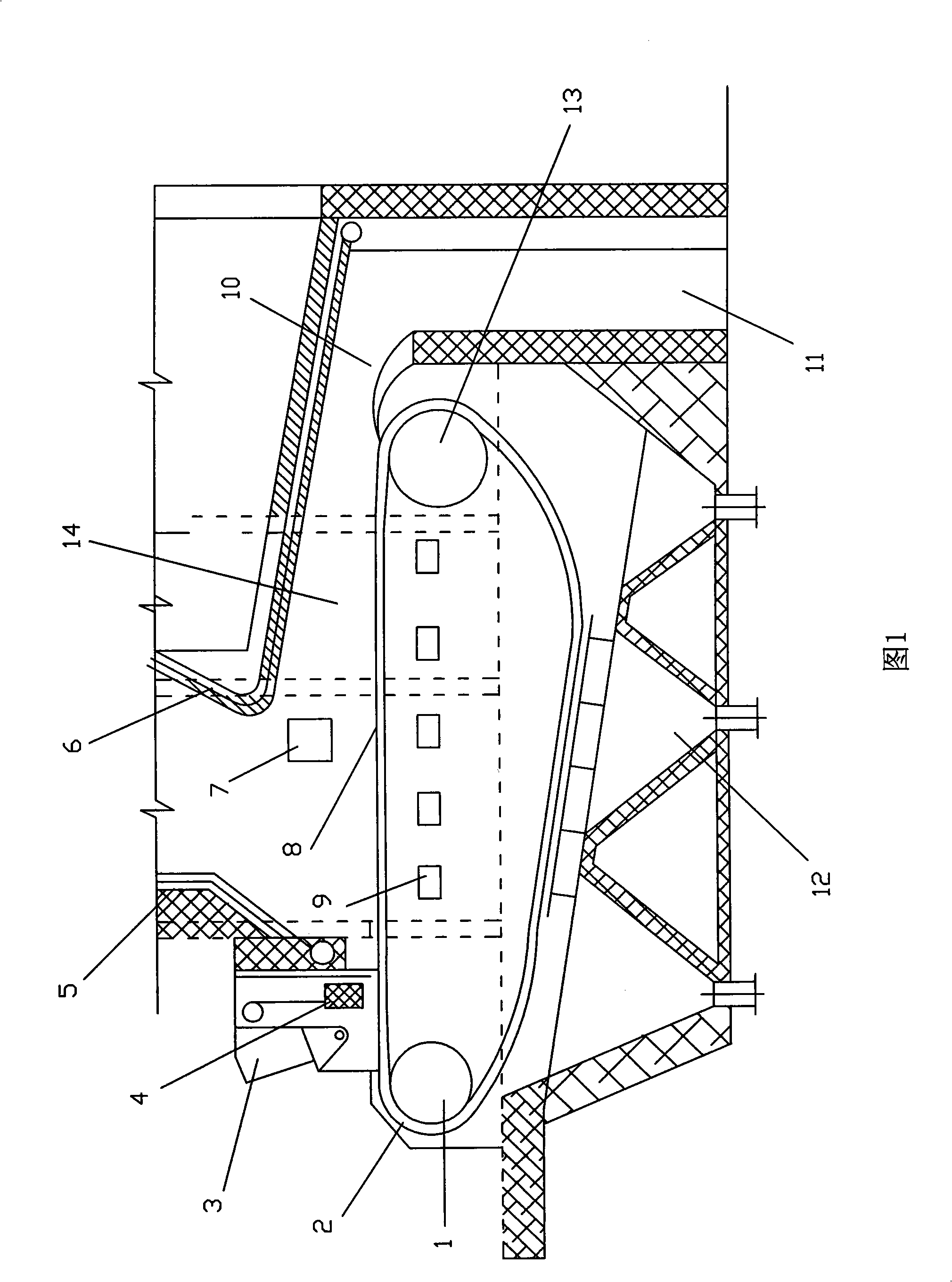
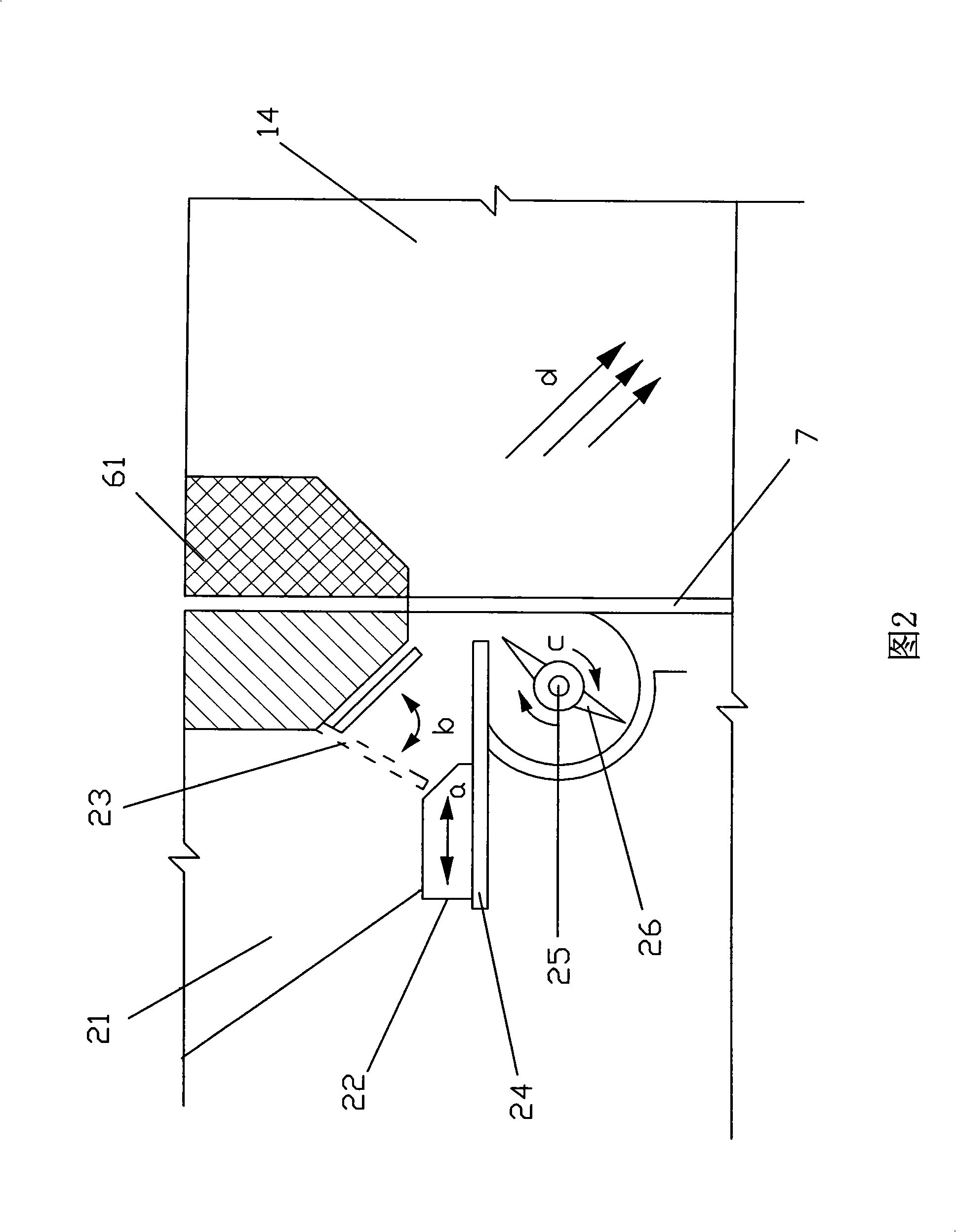
[0016] Referring to Fig. 1, the method for incinerating sludge in the chain furnace adopts a sludge throwing inlet 7 at the back arch of the side of the chain furnace, and coal and sludge are added to the hearth 14 of the chain furnace respectively. The coal is fed into the chain grate 2 of the chain furnace from the coal hopper 3 located in front of the furnace through the coal gate 4, and the coal is preheated, dried, and ignited sequentially with the movement of the chain grate 2; Sludge with a content of 15% to 60% is evenly added to the chain furnace from the sludge throwing inlet 7, and the sludge falling point 8 is located at the tail of the chain furnace hearth 14, which is one-half to three-quarters of the chain furnace grate 2 Near the rear arch 6, the sludge added here utilizes the furnace temperature at the end of the chain furnace h...


PUM


Abstract

The invention discloses a method for burning sludge in chain grate. A sludge feeding port is arranged on rear arch on the side surface of the chain grate used in the method; and coal and sludge are respectively added into the furnace of the chain grate. The method comprises following steps: adding the coal into the grates of the chain grate through a coal valve from a coal scuttle in front of the chain grate; preheating, drying, and burning the coal sequentially along with the movement of the grates of the chain grate; uniformly adding the squeezed and dewatered sludge alone from the sludge feeding port into the chain grate, wherein the sludge falls onto the grates in a position in the vicinity to the rear arch at 1/2 to 3/4 the tail section of the furnace of the chain grate; and igniting and burning the sludge added in the position by the temperature of the tail section of the furnace of the chain grate when the coal burning is substantially ended, wherein the added amount of the sludge is calculated and adjusted in real time according to the heat value of the coal and the temperature when the added amount is stabilized. The chain grate can ensure complete burning of coal when used for burning various kinds of sludge with heat energy utilization value, thus effectively utilizing the heat value of the sludge and improving the heat efficiency of the chain grate.

Description

technical field [0001] The invention relates to a method for incinerating sludge, in particular to a method for incinerating sludge in a chain furnace, which is suitable for incinerating and treating various sludge with heat energy utilization value. Background technique [0002] The chain furnace is used to incinerate all kinds of sludge with heat energy utilization value. The existing technology is to mix the sludge with coal and use a coal thrower to send it from the coal hopper to the chain furnace. Sludge and coal enter the furnace at the same time. Because the sludge has more volatile matter and less fixed carbon, and most of the volatile matter is fibrous and has a large porosity, the sludge burns faster than coal. If the grate speed is reduced according to the sludge combustion characteristics, there will be insufficient heat source, resulting in problems such as unstable furnace temperature and lower boiler steam pressure; if the grate speed is increased, although t...

Claims


Application Information

Patent Timeline
Patent Type & Authority Applications(China)
IPC IPC(8): F23G7/14F23G5/50
Inventor 唐志超李晓整胡杭滨
Owner ZHEJIANG HUAZHANG TECH
Why Eureka
Try Eureka