Plant and process for removing carbon dioxide from gas streams

A technology of carbon dioxide and gas flow, applied in chemical instruments and methods, separation methods, liquefaction, etc., can solve the problems of insufficient amplification, large quantities, etc.

Inactive Publication Date: 2008-12-17
CO2CRC TECH PTY LTD
View PDF0 Cites 27 Cited by
  • Summary
  • Abstract
  • Description
  • Claims
  • Application Information

AI Technical Summary

Problems solved by technology

Another difficulty is that a large amount of energy, about 30-40% of the total production of coal-fired power plants, will be required to release the carbon dioxide from the solvent or solid absorption medium after separation from the flue gas
In addition, technologies such as membrane separation have not yet been scaled up sufficiently to capture CO2 at coal-fired power plant scale

Method used


Image

  • Plant and process for removing carbon dioxide from gas streams
  • Plant and process for removing carbon dioxide from gas streams
  • Plant and process for removing carbon dioxide from gas streams

Examples


Embodiment 3 and 4

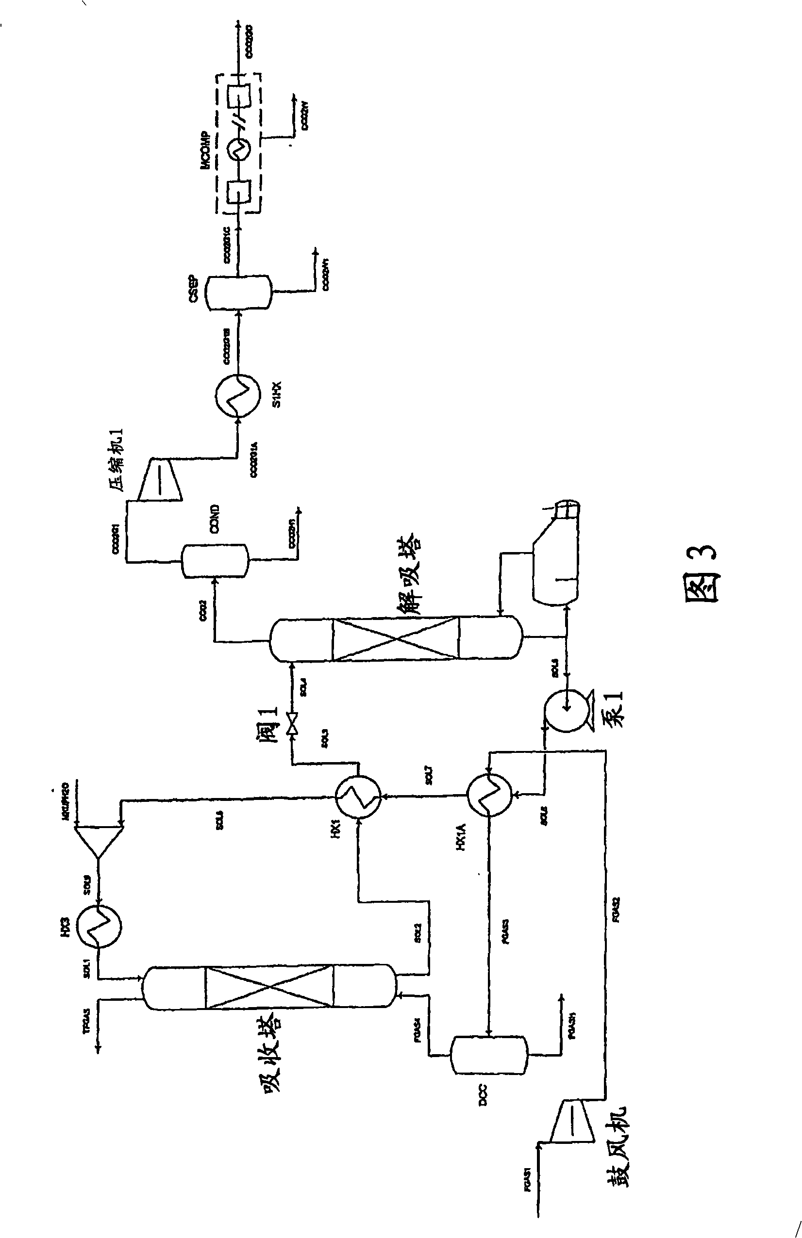
[0129] The flowchart shown in Figure 3 is similar to figure 2 The flow diagram is shown and includes the absorber, desorber and reboiler as well as several other unit operations, such as fans, designed for handling flue gases from lignite fired power plants. In summary, a flue gas stream designated FGAS4 that has been pretreated in a direct contact cooler (DCC) (essentially a knockout drum used to remove condensate) and heat exchanger HX1A is fed to absorption tower. The treated carbon dioxide-depleted flue gas is withdrawn from the absorber as stream TFGAS, and the carbon dioxide-depleted solvent stream is fed to the absorber as stream SOL1, and the carbon dioxide-enriched solvent stream is fed as stream SOL2 to the absorption tower. The carbon dioxide-rich stream SOL4 is fed to the desorption column via a throttle valve, and the carbon dioxide-depleted stream SOL5 is returned to the absorption column via heat exchangers HX1A, HX1 and HX3. A stream enriched in carbon dioxid...


PUM


Abstract

The present invention is based on the realization that the carbon dioxide component of industrial gas streams also containing steam can be processed so to utilize either as latent and / or sensible heat the heat available from the steam component to assist in separating carbon dioxide from the remainder of the gas stream. For example, flue gases produced by power stations burning brown coal, black coal or natural gas inherently contain a useful amount of energy that can be harnessed according to the present invention. According to particular preferred forms of the invention, nitrogen and sulphur constituent such as SOx and NOx, H2S and other nitrogen containing compounds may also be removed from the gas stream through direct contact with the absorbing medium and used to produce by-products such as fertiliser material.

Description

Background of the invention [0001] The present invention relates to apparatus and methods for removing carbon dioxide from industrial gas streams and effluents in order to reduce the release of carbon dioxide to the environment. [0002] In the last 150 years, the concentration of carbon dioxide in the atmosphere has risen from 280 ppm to 370 ppm, mainly from the increased use of fossil fuels, especially for power plants and transportation. However, it would be costly, economically damaging, and currently technically impractical for consumers to quickly switch to meeting all energy needs with alternative renewable energy sources. [0003] There is a need to reduce the emission of carbon dioxide to stabilize and reduce the concentration of carbon dioxide in the atmosphere in the long run. Promising technologies for significantly reducing emissions from large-scale CO2-emitting installations such as coal-fired power plants, cement plants, gas processing facilities, and iron sme...

Claims


Application Information

Patent Timeline
Patent Type & Authority Applications(China)
IPC IPC(8): B01D53/14B01D53/96B01D53/18F25J3/02
CPCY02C20/40
Inventor B·胡珀G·斯蒂文斯S·肯蒂什
Owner CO2CRC TECH PTY LTD
Why Eureka
Try Eureka