Optical engine apparatus capable of displaying stereopicture

An optical engine and stereoscopic image technology, applied in the field of optical instruments, can solve the problems of high cost, complex implementation process, and large volume

Inactive Publication Date: 2008-12-24
宁波市科技园区华域电子有限公司
View PDF3 Cites 1 Cited by
  • Summary
  • Abstract
  • Description
  • Claims
  • Application Information

AI Technical Summary

Problems solved by technology

Although realize stereoscopic projection with a projector, its volume is big, cost is high, and the process of realizing is much more complicated than the present invention

Method used


Image

  • Optical engine apparatus capable of displaying stereopicture
  • Optical engine apparatus capable of displaying stereopicture
  • Optical engine apparatus capable of displaying stereopicture

Examples


Embodiment 1

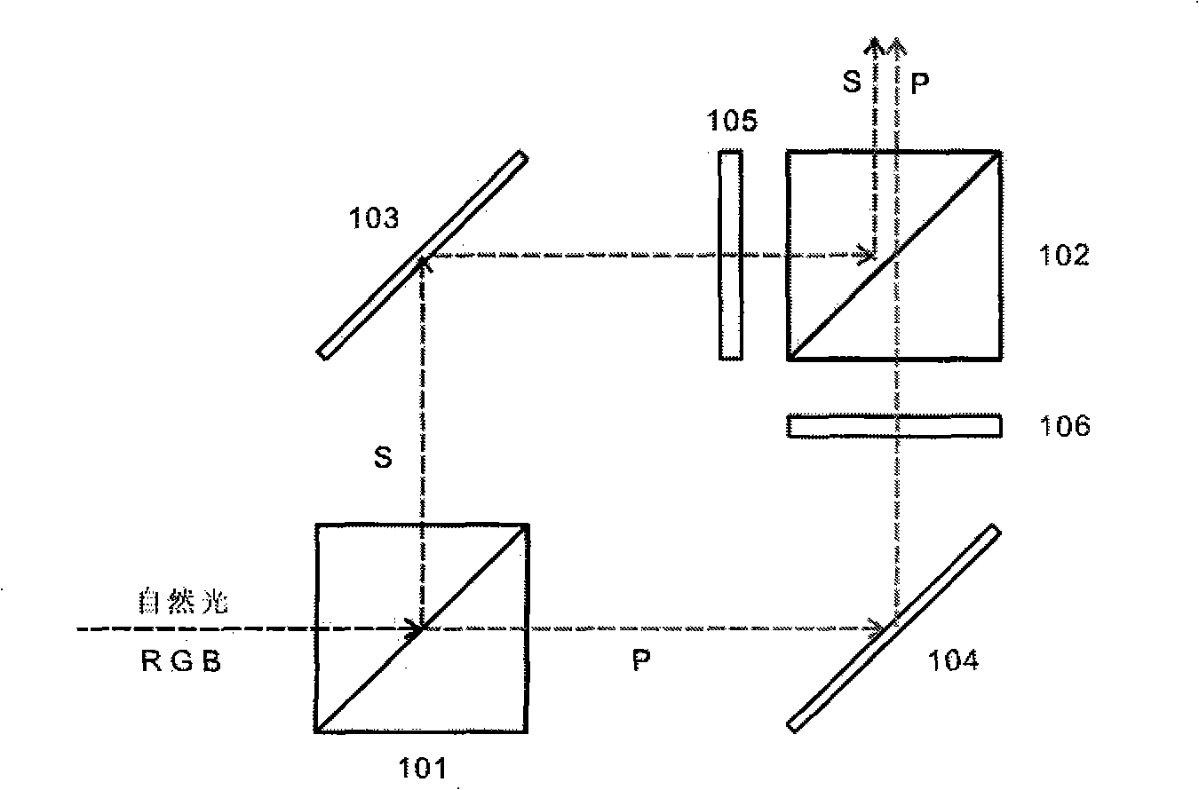
[0019] Embodiment 1, with figure 1 Shown, the present invention comprises two LCD105,106, two PBS101,102 and two planar reflecting mirrors 103,104, and its working characteristic is as follows, natural light is decomposed into two roads through PBS101, P light enters liquid crystal 106 through reflecting mirror 104 and carries out Optical modulation of image signals. The modulated P+S natural light signal is synthesized under the action of the polarizing crystal PBS102 in the film inspection and enters the lens system for imaging. The two LCDs 105 and 106 of the present invention are synchronized and modulated with the input signals R, G and B. Its main points: ① enter LCD106, 105 with P light or S light respectively by monochromatic light, as red (R) at the same time, because LCD106, 105 scans different half-screens respectively, output full-frame image light modulation signal at PBS102, Then go through R, G, B wheel color display. Therefore, compared with the original sin...

Embodiment 2

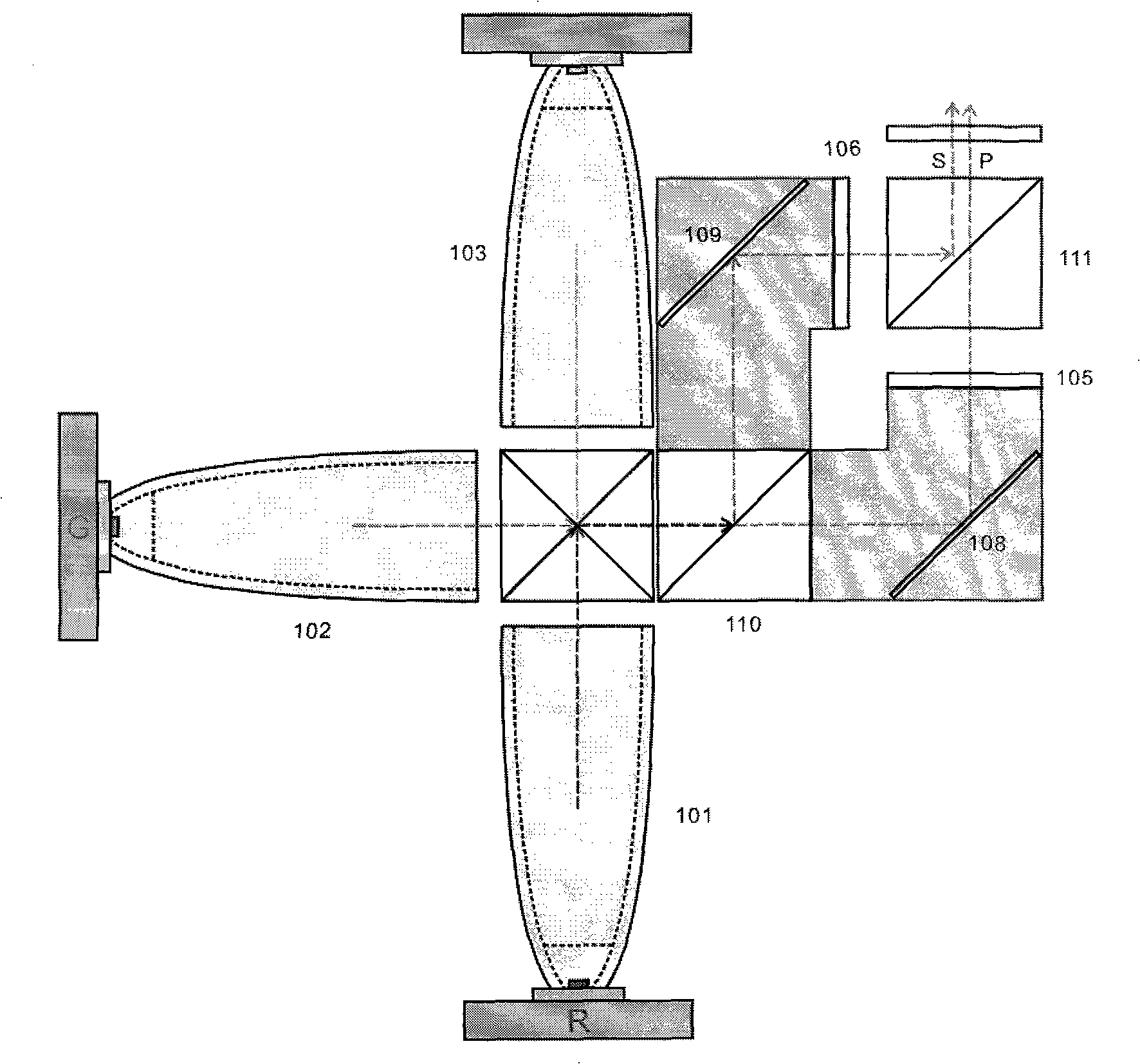
[0020] Embodiment 2, with figure 2 Shown in is also the optical-mechanical scheme of the equi-pathlength optical path. exist figure 2 Among them, the R, G, and B light rays combine colors in the color combining prism (104) through the CPC, and then are decomposed into P light and S light by the polarizing PBS110, and enter the LCDs 105 and 106 respectively. Since each LCD only needs half-screen scanning, The full-frame image can be synthesized in the polarization analyzer PBS111; therefore, its scanning speed is doubled compared with that of a single LCD, reaching the minimum frequency requirement required by the human eye, and the image or color no longer flickers. Also due to the independent modulation of P and S light, when viewing, the left and right eyes use different polarizer eyes to observe stereoscopic images. 108 and 109 shown in the figure are optical path light pipes, and the inner wall is coated with a total reflection film. According to the characteristics o...

Embodiment 3

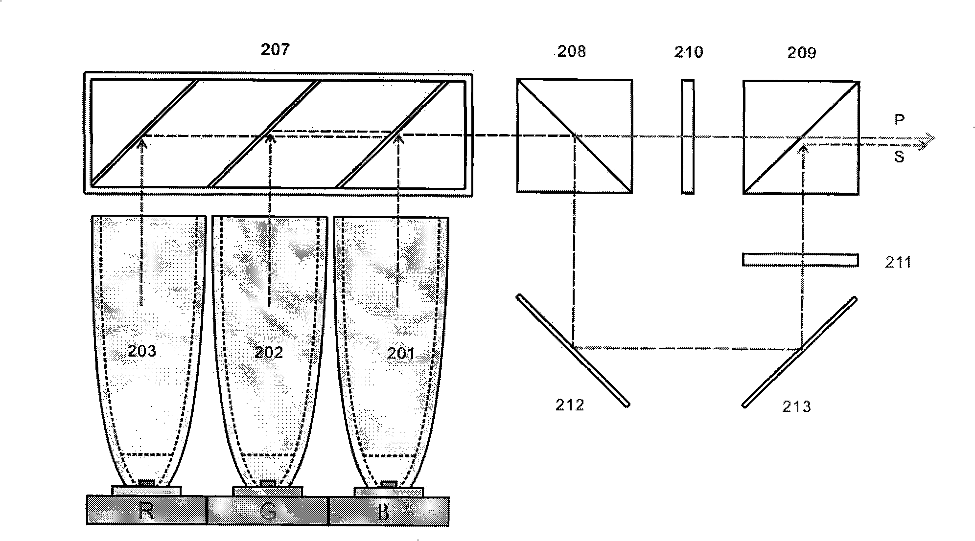
[0021] Embodiment 3, with image 3 Shown is the optical-mechanical scheme of the unequal optical path. As shown in the figure, R, G, and B pass through light guides 201, 202, and 203 and are decomposed into P and S lights in the PBS208 polarizer under the action of two-phase color plates 204, 205, and 206, wherein P light is directly Entering the LCD210, the S light is reflected by the mirrors 212 and 213 and enters the LCD211 and enters the polarization analyzer PBS209.


PUM


Abstract

An optical engine device which can display three-dimensional images adopts two LCDs, a natural light signal or a synthetic light signal passes through at least one polarization beam splitter PBS for decomposition to produce a P-path polarized light signal and a S-path polarized light signal; at least the P-path and the S-path polarized light signals respectively pass through two LCDs for image signal light modulation and then enter a same polarized light beam synthesizer PBS, the P plus S light signals after the modulation are synthesized under the PBS role to enter a lens system to form a three-dimensional image; the two LCDs and the input R, G and B light signals are carried out the synchronous modulation, namely, the single-color light enters the two LCDs by the P or the S light respectively and simultaneously, the two LCDs scan the different half screens respectively, a light modulation signal of the whole image is output after the synthesis by the polarized light beam synthesizer PBS, and the color display is carried out by passing R, the G and the B wheels; the optical engine device is characterized by simple structure, small size, low cost, faster scanning speed and higher light permeation efficiency, and the optical engine device can display a clearer three-dimensional image, etc.

Description

technical field [0001] The invention relates to an optical engine device capable of displaying stereoscopic images and increasing the scanning speed of an LCD, which belongs to optical instruments. technical background: [0002] Projectors using spatial light valve projectors such as digital micromirror device (hereinafter referred to as "DMD"), transmissive liquid crystal display (hereinafter referred to as "LCD"), and liquid crystal emitting on silicon (hereinafter referred to as "LCOS"), etc. Digital projection system. These displays are highly regarded due to their ability to provide standard display performance such as high resolution, wide color gamut, high brightness and high contrast ratio. The "DMD" solution represented by the US TI company and the 3LCD solution represented by the Japanese EPSON company are both mature technical solutions. They are widely used in the market, but due to their relatively expensive price and large size, they are currently There are f...

Claims


Application Information

Patent Timeline
IPC IPC(8): G02B27/28G02B1/10G02B27/10H04N13/00
Inventor 施振浩
Owner 宁波市科技园区华域电子有限公司
Why Eureka
Try Eureka